


Message 1 of 15
- Mark as New
- Bookmark
- Subscribe
- Mute
- Subscribe to RSS Feed
- Permalink
- Report
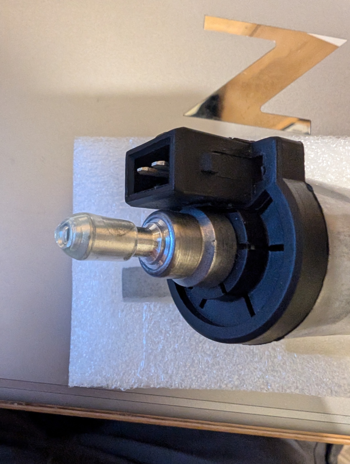
I'm trying to design a cover for a diesel heater pump.
Basically I'll draw the profile.
Then sweep (possibly not the right tool name) round the axis 180 degrees to create two halves.
I've created the profile (the lower line) then created a 2mm offset (at the left of the diagram)
I've then gone in to try and make the offset slightly bigger at 4mm, to give it more thickness.
But all of the points/dimensions then rotate.
I'm assuming those points/lines need somehow locking, but I'm confused as to how or why.
The dimensions should work out the length and height of each, and I just assumed everything would work off them, remaining at 90 degree angles.
Apologies .. I'm a beginner.
Thanks in advance.
Solved! Go to Solution.
