Chamfer at 60 degrees of really complex shapes

Chamfer at 60 degrees of really complex shapes

gneF9AUM
Participant Participant
2,912 Views
13 Replies
Message 1 of 14

Chamfer at 60 degrees of really complex shapes

gneF9AUM
Participant
Participant

Good day,

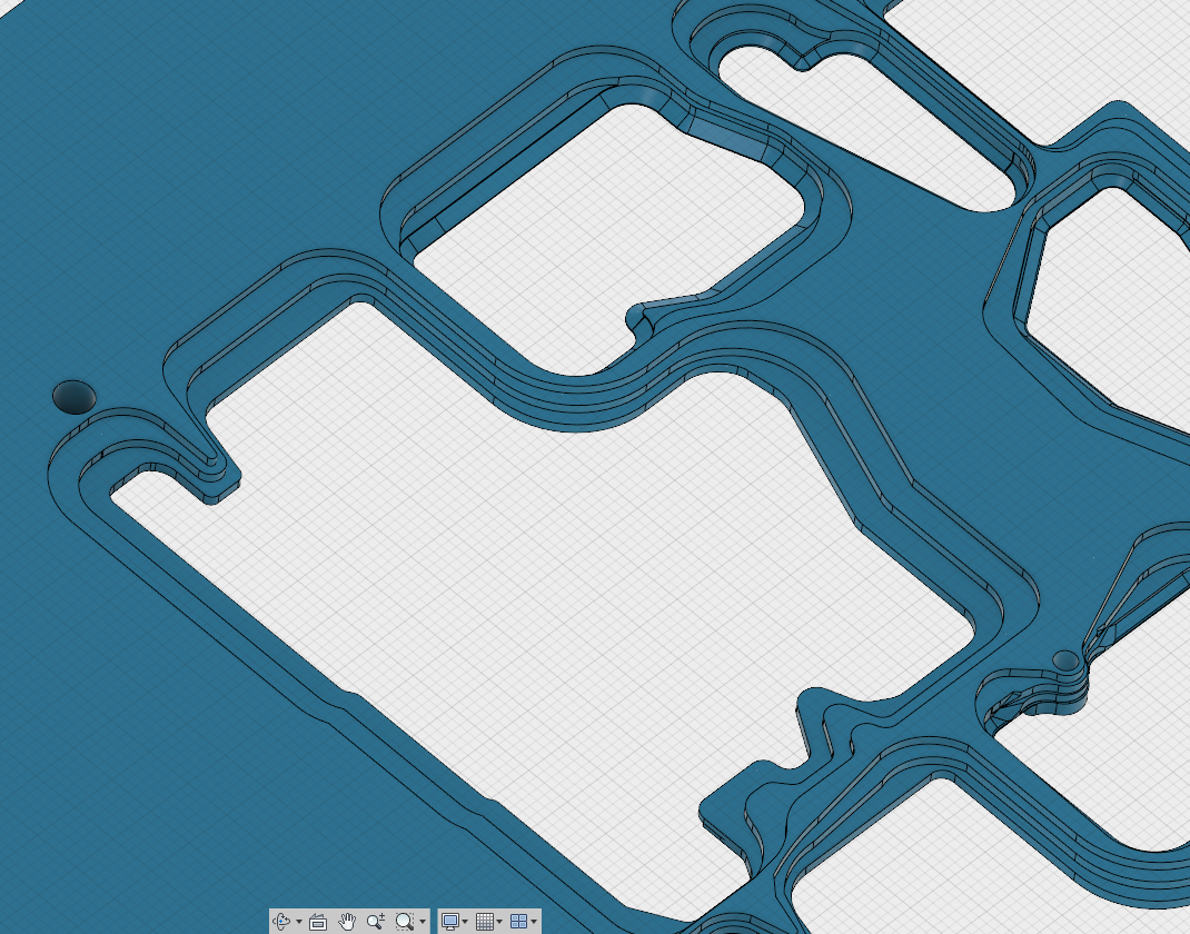
I am busy cutting a solder tray for PCB manufacture. One of the requirement is that the bottom of the tray, that lies against the PCB, at the area that will be exposed to the solder wave, be chamfered at 60 degrees.


The problem is that some of the step faces are to small to accept a 60 degree chamfer and that is where it ends. Fusion will not identify the areas it cannot do. is it possible to chamfer the areas it can at the max length and angle and the areas it cant, just leave out.


I have been able to do it manually, by projecting the hole through the tray to the bottom of the tray. Then I extrude the sketch with a 60 degree angle. Now I have a large plug with 60 degree angle. I take the projected sketch and create an offset that stays within the bounds of the steps on my object. I extrude that up subtracting it from my plug.

The plug now has 60 degree corners but fits into the bounds i need. I move it down into position, into the hole, cutting off the corners with the 60 deg edge, and subtract it from the main. leaving me with, mostly the desired effect.


Problem is it takes forever. there must be another way to do this?


thanks


0 Likes
Accepted solutions (1)
2,913 Views
13 Replies
Replies (13)
Message 2 of 14

SaeedHamza
Advisor
Advisor

Hi,


Could you please file>export>.f3d and then attach you design to you next post


Regards


Saeed

Saeed Hamza
Did you find this post helpful? Feel free to Like this post.
Did your question get successfully answered? Then click on the ACCEPT SOLUTION button.

EESignature

0 Likes
Message 3 of 14

etfrench
Mentor
Mentor

Have you tried deselecting 'Tangent Chain' in the chamfer dialog? It should be pretty straight forward (although time consuming and tedious) to just select the boundaries that are wide enough for the chamfer.


An easier way to find the invalid boundaries is to start a new sketch. Project the inner boundary and the first step boundary. Calculate the width of the 60 degree chamfer at the first step height. Offset the inner boundary that width (Note: you can use a formula for the calculation).  Anywhere the offset line crosses the first step boundary is not valid for the chamfer.


p.s. Investigate the API for automating this.

ETFrench

EESignature

0 Likes
Message 4 of 14

gneF9AUM
Participant
Participant

Hi,

Thank you for looking at this.  🙂

Please see attached file. I hope it is still usable as i have been messing with it.


thanks


0 Likes
Message 5 of 14

gneF9AUM
Participant
Participant

Hi,

thanks for the reply.

Tried that now.

But it is a bit frustrating in that you have to select everything before you commit the change. If you have not selected enough you cannot continue after it commits a change and if you have not selected enough same problem. i get better result with my subtracted plug.


once an area has been half chamfered i.e. chain x has been chamfered, then chain x+1 cannot be chamfered anymore because some of its geometry has changed.

I will play around a bit more see if i can fiddle it in a different way. 


If i am going to project the boundaries i might as well draw my plug. I am not too concerned if some of the geometry is messed up by the chamfer. There should be a strict setting and a non-strict setting. strict i want the algorithm to preserve all geometry and non-strict i don't care what happens toward the top as long as you don't make the bottom hole bigger.


thanks i do appreciate your comments and i will do some tests using them. sometimes you just need to develop a feel for something to make it work. 

0 Likes
Message 6 of 14

michallach81
Advisor
Advisor

To add more edges after size is specified you need hold the Ctrl key, that would suspend execution of preview and will let you add more edges.


Michał Lach
Designer
co-author
projektowanieproduktow.wordpress.com

0 Likes
Message 7 of 14

SaeedHamza
Advisor
Advisor
Accepted solution

Hi,


Since chamfer doesn't work, try using a sweep

Watch this please


Regards


Saeed

Saeed Hamza
Did you find this post helpful? Feel free to Like this post.
Did your question get successfully answered? Then click on the ACCEPT SOLUTION button.

EESignature

0 Likes
Message 8 of 14

WHolzwarth
Mentor
Mentor

I've made an attempt with Loft in Inventor. IMO, creating this shape following the existing sketches is impossible.

Smiley Wink But I'm watching comments from other members

Walter Holzwarth

EESignature

0 Likes
Message 9 of 14

TrippyLighting
Consultant
Consultant

It may have helped it you named the bodies so your design is easier to analyze.

What did you intend to achieve with this triple stepped approach ?

Where are the cut-out features that create all the big openings ?


EESignature

0 Likes
Message 10 of 14

TrippyLighting
Consultant
Consultant

How are you going to manufacture these infinitely thin surfaces on the poor side of your designs ?

Screen Shot 2017-06-13 at 9.21.39 PM.png


EESignature

0 Likes
Message 11 of 14

gneF9AUM
Participant
Participant

Hi. 

i imported the 3D drawing from turbocad and there are a few little issues like this. But that is not a problem at this stage. i have to design 7 separate trays and i cannot spend 2 weeks on each different design. Also learning fusion now, so there are probably 100 other mistakes 10 times worse than that 🙂


thanks 

0 Likes
Message 12 of 14

gneF9AUM
Participant
Participant

Hi,

thanks. this is what i wanted to do, or lofting, but did not know about these extra features like set plain along path and sectioning into the drawing.


I will try tonight.


I will let you know tomorrow.


thanks

0 Likes
Message 13 of 14

gneF9AUM
Participant
Participant

Hi,

The only reason for the triple stepping approach is because i have never been able to "hollow" out the tray as i would like without some exotic complicated fiddling. They normally use a bull nose to level down from the bottom to where the wave solder hole is. that is where i am heading hopefully.

Also solder is hopefully viscous enough to ignore all the steps. 

0 Likes
Message 14 of 14

etfrench
Mentor
Mentor

Since you have more designs to do, it would pay to learn how to do them correctly. Using either Sweep or Pattern on Path with the profile of the bullnose bit would be much better than the steps you're using.  When it comes time for machining these, you'll find that it will be much more accurate and faster to use the bullnose bit.  The chamfers you have currently modeled will not be able to be machined completely as you have not allowed for the width of the chamfer tool.


ETFrench

EESignature

0 Likes