Image 2 Surface Script for Fusion 360

Image 2 Surface Script for Fusion 360

hanskellner
Autodesk Autodesk
28,224 Views
79 Replies
Message 1 of 80

Image 2 Surface Script for Fusion 360

hanskellner
Autodesk
Autodesk

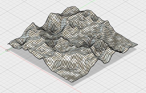
I've created a script for Fusion 360 that can be used to import an image and convert it to a mesh, sketch points, or sketch lines.


The following heightmap image of a portion of the moon was used to generate the following mesh and then t-spline:


Moon.jpg => MoonMesh.png => MoonTSpline.png


The t-spline version is the most flexible for changes and it can also be used in the CAM environment for milling.


The code and information is posted on Github:


https://github.com/hanskellner/Fusion360Image2Surface 


Note, because of limitations in Fusion on the size of meshes, I highly recommend using only very small images. For example, the moon image above is only 50x50 pixels. If you have an image that's large then create a smaller version of it then import that.


Cheers,


Hans


Hans Kellner
Senior Manager, Principal Engineer
Accepted solutions (3)
28,225 Views
79 Replies
Replies (79)
Message 61 of 80

zimri2000
Observer
Observer

Dug deeper and I was using display port, which was causing the issue. Once I hooked directly to my graphics card it worked. 

Message 62 of 80

Anonymous
Not applicable

I am getting the same popup error on Windows

Error.JPG

0 Likes
Message 63 of 80

daniel_lyall
Mentor
Mentor

Are you using the new or old UI


Win10 pro | 16 GB ram | 4 GB graphics Quadro K2200 | Intel(R) 8Xeon(R) CPU E5-1620 v3 @ 3.50GHz 3.50 GHz

Daniel Lyall
The Big Boss
Mach3 User
My Websight, Daniels Wheelchair Customisations.
Facebook | Twitter | LinkedIn

0 Likes
Message 64 of 80

BrianEkins
Mentor
Mentor
Accepted solution

Based on the error you're getting, try setting your document to "Capture design history". If you right-click on the top node in the browser it's the last command in the context menu.

---------------------------------------------------------------
Brian Ekins
Inventor and Fusion 360 API Expert
Website/Blog: https://EkinsSolutions.com
Message 65 of 80

hanskellner
Autodesk
Autodesk

@BrianEkins - Yes, you are correct.  The addin requires the document to be capturing design history.


I've just updated the addin (on Github) with a change that checks that this mode is set and if not then it will display a dialog indicating the problem.


Thanks,


Hans


Hans Kellner
Senior Manager, Principal Engineer
0 Likes
Message 66 of 80

Anonymous
Not applicable

hello,


i use your image2surfave add in and it works great... except for the following case and i dont understand why...

I hope you can help because its for school. I need an 3d drawing of a Carolus Daalder. its a coin.

i have an image and when i load it in. it looks great. but after generating the surface all the contours aren visible at all.

do you know a fix? I hope so.

i will post my picture a an attachement.


Message 67 of 80

hanskellner
Autodesk
Autodesk

I did a quick test with your image and was able to generate a surface with detail.  For the Image2Surface settings I used:


Pixels to Skip = 1

Stepover = 2

Max Height = 10

Smooth = Checked


Here's the file: https://a360.co/2ThlMD9 

Screen Shot 2019-02-25 at 3.29.11 PM.png


Hans Kellner
Senior Manager, Principal Engineer
0 Likes
Message 68 of 80

Anonymous
Not applicable

Hi,


Thanks for creating this script. It is great to have this functionality.


Perhaps this is some mistake in my configuration, but the surface mesh that is generated on my system always consists of triangles. Since it's not a quad mesh, the Fusion 360 will not convert it to T-Spline body, which I would like to use further in my workflow.


I'm wondering how to fix this? As a reference I have included screenshots of the surface I'm working with. The preview in the Image 2 Surface GUI seems fine, but the result after it's sent to the Fusion not anymore. 


Image 2 SurfaceImage 2 SurfaceFusion 360Fusion 360

0 Likes
Message 69 of 80

hanskellner
Autodesk
Autodesk

I've just done a test and verified that the surface is correctly created within Fusion using quads and not triangles.  I would like to better understand your exact workflow.


What workspace are you in when you launch the Image 2 Surface add-in?  I'm assuming the Model workspace as the add-in should only run when that is active.


If you try another image, do you still get triangles on generation?  Note, there's the sample "resources/MoonHeightmap.jpg" in the Image2Surface add-in folder that you can try.


Thanks.


Hans Kellner
Senior Manager, Principal Engineer
0 Likes
Message 70 of 80

Anonymous
Not applicable

I'm launching the Image 2 Surface GUI from the Model workspace, immediately after starting the Fusion 360 and running the add-in from the "Scripts and Add-Ins" dialog. (I verified that I indeed cannot launch it from different workspaces.) Capture of the Design History is on. There are no other special add-ins or scripts that I'm using.


As you suggested, I tried the "resources/MoonHeightmap.jpg" and "resources/samples/penny_depthmap_500-sm.jpg" images, and got the same behaviour as previously - only triangles on generation in both cases.


0 Likes
Message 71 of 80

hanskellner
Autodesk
Autodesk

Ok, I think I know what might be the issue.


There is a Mesh setting in the Fusion 360 preferences to triangulate mesh polygons.  I'm guessing that you have that setting enabled.  Try unchecking/disabling that setting then creating a surface.


Hans Kellner
Senior Manager, Principal Engineer
Message 72 of 80

Anonymous
Not applicable

That was it! Thanks a lot for your help!

0 Likes
Message 73 of 80

sdj544
Observer
Observer

Love this script and what it allows me to do with logos and photos.


I'm just a little confused on what the 'stopover' setting should be doing.

I assumed it would just change the resolution and give a finer tool path , but it's also changing the height.

When I have the max height set to 10mm and change it from 1 to .5 the depth of the mesh created also doubles to 20mm.  

Is it supposed to do this? Or does changing the stepover to less than 1 increase the quality of the mesh. 

My final output is with a 1mm bit and .5mm stopover, which is why I trying to use those settings.


thanks!

Steve


0 Likes
Message 74 of 80

hanskellner
Autodesk
Autodesk

Hi @sdj544 -


Very glad to hear the script is helping you.


The script is converting a grid (or mesh) of pixels from an image into a grid (or mesh) consumable by Fusion.  When converting from the pixel grid to the mesh surface, it uses the settings as such:


Pixels to Skip : How many pixels to ignore as the script steps across and down the pixel image to generate the mesh.  This is essentially reducing the resolution/quality of the image.  Assume you have a 1000x500 pixel image.  Setting this value to 10 will cause the script to use every 10th pixel: X dimension 1000/10 = 100 pixels and Y dimension 500/10 = 50 pixels.  Therefore, the mesh that will be created within Fusion will be 100 x 50.


Stepover: The stepover indicates how far apart each gridline will be in the mesh that's created.  If you set the stepover to 2mm, then for the 100 x 50 grid in the example above, the script will create a mesh that is (100 * 2mm) x (50 * 2mm) or a 200mm x 100 mm mesh.


Max Height: The height at each node in the mesh/grid is determined by the color/brightness of the pixel and the max height value.  The color of the pixel is normalized (0 to 1) and then multiplied by the Max Height value.  A black pixel would generate a height of 0 whereas a white pixel would generate a height of Max Height.  This makes the most sense for height map images in which heights are mapped to gray scale.  For colored images the color value is also normalized but it does so by calculating a brightness (0 to 1) and then multiplying by the Max Height.


For the issue of the mesh depth exceeding your specified Max Height, I'm not sure what is occurring.  I'll have to to some testing.  At first I thought the issue was caused by changing the stepover which causes it to select different pixels whose "height" is different from the pixels selected when using another stepover value.  For example, one stepover value may cause a set of black pixels to be selected while another stepover causes white pixels to be selected.  But even in that case, the code should be limiting the mesh height from 0 to Max Height.


I'll do some checking and see what I find.


Thanks.


Hans Kellner
Senior Manager, Principal Engineer
Message 75 of 80

sdj544
Observer
Observer

Thanks for the quick response!


It's not hard to do a workaround and just resize to flatten it, but just wanted to make sure there wasn't something I was missing that would increase the quality of my work.


One other question as to functionality.  I have a circular logo without a background and when I import it it still ends up being square. It interprets no background the same as black and creates a skirt at the lowest level. I'm using PNG files currently. I've tried jpg, tiff etc. and they all do the same thing. Is there some way to do this that I'm missing?


thanks!

-S


0 Likes
Message 76 of 80

hanskellner
Autodesk
Autodesk

Hi @sdj544 -


The mesh created for a surface will always be rectangular.  To crop a mesh surface so that it only contains the circular portion of your logo:

  • Import your image into Fusion using the Image 2 Surface add-in
  • Convert the mesh to a T-Spline
  • Create a sketch that is on the same plane as the t-spline
    • Draw a circle that encloses the portion of the surface you wish to keep.
    • Draw a rectangle around the outside of the t-spline surface.
    • Exit the sketch
  • Select the profile formed by the circle and rectangle (not the portion within the circle)
  • Select Extrude and in the dialog, choose "Cut"
    • Drag the extrude distance so that it is taller than the height of your t-spline surface
    • Click OK

You should now have a T-Spline surface that is circular and contains your logo.


Hans Kellner
Senior Manager, Principal Engineer
Message 77 of 80

nlvaluke
Community Visitor
Community Visitor

When following these steps, Fusion does not all me to select the script. It is greyed out.

0 Likes
Message 78 of 80

hanskellner
Autodesk
Autodesk

Hi @nlvaluke -


You should only need to select the folder containing the script.  Fusion should then be able to find the script/addin and install it.


Hans Kellner
Senior Manager, Principal Engineer
0 Likes
Message 79 of 80

jay_gledhill
Community Visitor
Community Visitor

I'm having a lot of trouble using this tool.
Fusion is telling me that the mesh is not closed. and no amount of effort in attempting to get fusion to repair the mesh is working.

And I'm having a great deal of trouble trying to combine it as an intrusion to make a "cut" out of the surface I'm trying to "engrave"

I'm quite the noob to Fusion, but in the short amount of time I've been using it, I've made great strides in progress. However, this has trully stopped my progress dead in it's tracks

0 Likes
Message 80 of 80

RandyKopf
Collaborator
Collaborator
It's actually a very outdated unsupported under realized offer. Your be better suited using something more suited to meshes liker ZBrush.

Randy Kopf 

http://desktopartisan.blogspot.com/


If my post is helpful, press the LIKE Button If it resolves your issue, press Accept as Solution! Have a great day!
0 Likes