A custom gear shape design

A custom gear shape design

BillGEGHV
Advocate Advocate
2,667 Views
27 Replies
Message 1 of 28

A custom gear shape design

BillGEGHV
Advocate
Advocate

Hi All,  I'm wondering if anyone can give me any input on creating a simple custom gear/arrangement that I can change parametrically. The goal being to be able to change the tooth count and shape of teeth on the fly without having to redraw everything over and over. Im just not that good yet at constraints and perametics    ;  { 


2nd requirement is that the gear shape needs to be pretty close to what I have already, as the larger gear is actually a thumbwheel that will be turned by your thumb to make setting changes to a machine. SO the gear needs to feel confortible when turning by your thumb or finger. 


3rd requirement is the final gears need to be CNC machined from top and bottom ONLY in aluminum and are quite small so I will need to finish with 1/8 end mill to get into the pocket without any axial undercuts of the gear teeth.  


Any input would be appreciated. 

0 Likes
2,668 Views
27 Replies
Replies (27)
Message 2 of 28

jhackney1972
Consultant
Consultant

Please attach the Fusion 360 model that you have done and/or please attach your design specifications.  If you do not know how to attach your Fusion 360 model follow these easy steps. Open the model in Fusion 360, select the File menu, then Export and save to your hard drive. Then use the Attachments section of a forum post to attach it.

Attachment.jpg

John Hackney, Retired
Did you find this post helpful? Feel free to Like this post.
Did your question get successfully answered? Then click on the ACCEPT SOLUTION button.

EESignature

0 Likes
Message 3 of 28

BillGEGHV
Advocate
Advocate

I can't upload the design its a proprietary product. I included images isn't that enough to evaluate what I need. 

0 Likes
Message 4 of 28

TheCADWhisperer
Consultant
Consultant

@BillGEGHV wrote:

I can't upload the design its a proprietary product. 


That’s proprietary? Or is the more hidden stuff that you could first separate out?

This is a very easy assignment that could be completed using only the pictures as reference, but the primary reason I would want to see your attempt is to gauge your understanding of basic sketching and parametric modeling techniques.

Otherwise my first instruction would be, “This is how you create a sketch circle, and so on…

0 Likes
Message 5 of 28

etfrench
Mentor
Mentor

You'll need to change the pitch diameter of one of the gears in order to make them fit with the same amount of backlash. The tooth circles on each gear need to be tangent.  You'll also need to decide how much backlash is needed to make a smooth running gear.

In this sketch, the smaller gear was designed with tangent circles. The common tooth circle between the two was patterned on the larger circle.  As you can see they are not tangent with each other.

RoundToothGear.JPG

ETFrench

EESignature

0 Likes
Message 6 of 28

BillGEGHV
Advocate
Advocate

For the large gear did you purposely draw them without tangency in order to get the offset space? and are you able to change the number of teeth on this with everything updating? 


When you did the pattern are you using the pitch di curve to array the circles on top of? IF yes I did not know you can do that in Fusion. In Rhino its array along curve.   


This is exactly what I did in Rhino to get this 1st version, but without any parmatics and not really even considering the math. NO Pi was used when creating them lol, I just kept tweaking the circle sizes and spacing till I got something that seemed to work.   


I think I just need to draw in Fusion it and just figure it out. 

0 Likes
Message 7 of 28

TheCADWhisperer
Consultant
Consultant

I would ot use a sketch pattern for this design.

0 Likes
Message 8 of 28

etfrench
Mentor
Mentor

These simple patterns don't stress Fusion 360. There also is no tangent joint for solid bodies.

ETFrench

EESignature

0 Likes
Message 9 of 28

etfrench
Mentor
Mentor

The large gear has the number of teeth in your first post's image.  I made a small mistake in the image I posted.  The small gear tooth circles were coincident with the endpoints of the radial lines instead of tangent to each other.  When tangent they will be smaller which means the large gear must also be smaller.  I'll make a screencast later tonight.

ETFrench

EESignature

0 Likes
Message 10 of 28

TheCADWhisperer
Consultant
Consultant

@etfrench wrote:

These simple patterns don't stress Fusion 360.


Let’s see you change the number of teeth using sketch pattern.

0 Likes
Message 11 of 28

etfrench
Mentor
Mentor

Here's the parametric version. Since the tooth and the valley are modeled as separate circles, the circular pattern tooth counts must be even numbers.

Here are the parameters:

RoundToothGearParameters.JPG


And the screencast:


ETFrench

EESignature

0 Likes
Message 12 of 28

etfrench
Mentor
Mentor

p.s.  The tooth size for the pinion gear was set by dimensioning the radius of the pitch circle (circle not shown).

ETFrench

EESignature

0 Likes
Message 13 of 28

TheCADWhisperer
Consultant
Consultant

I did not see a solid body update with change in number of teeth.

Can you File>Export your *.f3d file to your local drive and then Attach it here to a Reply?

0 Likes
Message 14 of 28

TheCADWhisperer
Consultant
Consultant

@BillGEGHV wrote:

The goal being to be able to change the tooth count and shape of teeth on the fly without having to redraw everything over and over.


@BillGEGHV , as you follow @etfrench lead in completing this design - I recommend that you sketch one tooth and pattern feature rather then sketch elements.  A pattern of sketch elements requires re-selection of the profile (which in this case would be relatively complex as a sketch pattern.  There are also computational efficiencies to pattern of features over sketch elements as well.


Here is an image of a couple of examples sort of related to your Design Intent.

On the left is an image of a standard Roller Chain Sprocket that is fully parametric with chain size and number of teeth.  (Compare the dimensions to the Machinery's Handbook nomenclature).  On the right is the true involute curve of a standard spur gear (Dimensions hidden for clarity - fully parametric for number of teeth and 14.5°or 20° pressure angle.  Note in both examples that only a single tooth is sketched.  Editing the named Parameters changes everything to update as expected.

As you run into difficulties - Attach a dummy example of your effort here.  (No proprietary information is needed to complete a general principles example of this design.)

Pattern TeethPattern Teeth

Edit: I thought maybe I should point out that these images were in a different program where the color scheme as blue is fully constrained.  You probably don't want blue geometry in your parametric sketch.  🤔


0 Likes
Message 15 of 28

etfrench
Mentor
Mentor

@TheCADWhisperer wrote:

I did not see a solid body update with change in number of teeth.


That isn't what you asked for previously.  Changing the goal posts is always a fun game😀


ETFrench

EESignature

0 Likes
Message 16 of 28

etfrench
Mentor
Mentor

Here's how it's done:

ETFrench

EESignature

0 Likes
Message 17 of 28

TheCADWhisperer
Consultant
Consultant

@etfrench wrote:

That isn't what you asked for previously.  Changing the goal posts is always a fun game.


Uhm, I didn't define the goal???


From the original problem description:


@BillGEGHV wrote:

 The goal being to be able to change the tooth count and shape of teeth on the fly without having to redraw everything over and over.


0 Likes
Message 18 of 28

BillGEGHV
Advocate
Advocate

God, I wish i would have gone to mechanical engineering school and got that degree "backup plan" as my dad suggested. BUT NOOOOOOO I wanted to work in the movies and be a special effects make-up guy. "all self taught" this is feeling so beyond me. LOL What do I need to really understand to make this work. Im 1/2 way there? I think? 20 years using Rhino has done me no good, but when you get to the point you understand perametrics it is the most rewarding thing ever!  


Once I get the pinion gear to where I like it I will probably not need to change it as I'm already locked in based on my end mill diameter and the internal room I have to work within my mechanism.  


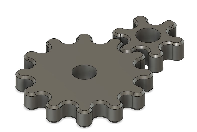
So this is what I have so far, but I'm stuck at this point. I can change the tooth count on the fly but that is just simply using a circular array. no biggie and not exactly what I need.   


I did don't think I mentioned it but when I said update when adding teeth I also meant the overall diameter of the gear needs to update at the same time. Which etfrench you have done exactly what im looking for. Probably took you 5 min. I'm tempted to ask you to share your design BUT that would not do me any good in the quest to understand and be able to do this on my own. I DO appreciate the mock up design and effort you've put in. Thanks   


SO, the question is what am I missing in my sketch? Im focused on the large gear at this point that is really the gear I need to do multiple iterations and prototypes to see what works. How do I constrain the overall diameter / "pitch diameter" to the tooth so they both update when making tooth count changes OR a change to the pitch diameter? I do realize that making random diameter changes would actually change the tooth diameter as well and is not necessarily the workflow I would follow, again the pocket needs to be a bit larger than 1/8 di for the end mill to fit in there for finish passes.   


How can I share just the gear geometry with you guys? I've never parted out a design like this to share only 1 or two components. FYI the gears are separate components. Would I have to make a copy of the file and strip out all but the gears? 


etfrench let me ask you something. When editing parameters did you customize the table in any way? OR are you just opening it up and changing the tooth count? What I want to understand is is there a need to be able to do expressions and customize the parameters to make this work? 

Parameters 2021-06-30 16.07.16.jpg

Parameters 2021-06-30 16.07.27.jpg


0 Likes
Message 19 of 28

BillGEGHV
Advocate
Advocate

One thing I keep asking myself as I work this out is do the small circles need to meet and intersect exactly on the pitch diameter circle in order to have the correct size small tooth circles? My common sense tells me they do need to? IF they do not then the offset or "backlash" is not going to be right? RIGHT? I do realize I can just adjust the offset/backlash with a simple offset or by making the tooth circles just undersize.


And If there is overlap from each curve on to the other does that matter? Something is telling me I don't want that BUT if you reduce the overlap then you end up with to much space between the circle edges? 

0 Likes
Message 20 of 28

BillGEGHV
Advocate
Advocate

another goal is to have the common or shared gear teeth FIXED and constrained and all gear teeth are added to the outside of it.

0 Likes