I'll give it a shot! Error T-Points are a fairly tricky & technical one to explain, so apologies in advance if this isn't very clear...
NURBS geometry (on which T-Splines is partially based) has a concept called 'knots' (sometimes referred to as 'spans'). NURBS curves & surfaces work by effectively tying a bunch of mathematically simple curves/surfaces together - using these knots - in order to form complex splines that couldn't easily be defined with a simple equation. NURBS curves & surfaces all have a hidden property called a knot vector, which is used behind-the-scenes to define the spacings between these knots. (It might be worth Googling "NURBS knots"/"NURBS knot vectors" for a fuller explanation; a quick search brought up this technical paper, which gives quite a good introduction).
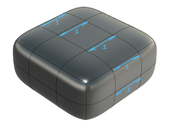
In T-Splines, you can think of each chain of edges as a knot in the T-Splines surface. The values for the spaces between the knots are actually arbitrary (it's the relative proportions between them that's important, not the actually values). So for this box, let's say the spacing between each pair of knots is 1 (here I'm just showing the knot spacings between two edge chains flowing in one direction; but you have the same thing between all pairs of edges in all directions):

If use Insert Edge to insert a single edge at the top of the box, it's going to add two new T-points, which effectively 'splits' the knot spacing here:

If I inserted this edge exactly halfway, the spacing between the new edge and neighbouring edges will be 0.5 on each side:

The numbers all add up nicely here, and I end up with two valid T-points.
A red T-point occurs when a split is created in a way that doesn't add-up nicely (i.e. where the topology doesn't allow for a 'sensible' knot spacing values). For example, I'll add an edge, but this time I'll use the Insert Point tool, and insert an edge from the midpoint on one side of the face to a corner on the opposite side (you can already see that this has given me a boxy result; '3' just indicates a 3-sided face here):

The reason that this T-point is 'bad' is that it has introduced an ambiguous knot spacing (at the yellow segment here):

Travelling along the highlighted chain of faces, the knot spacings from upper-left downwards dictate that the yellow segment should have a knot spacing =1. But travelling up from the bottom-right of the image, the yellow segment and purple segment must add up to 1. If the purple segment has a knot spacing of >0 (which really it needs to), the yellow segment must have a knot spacing of <1. We have a conflict on what the knot spacing of this yellow segment should be, and this is what causes this T-point to be erroneous, and prevents us for getting a legal smooth surface.
If this T-point it swapped for a star point, the 4-sided face with the T-point just becomes a 5-sided face:

N-gons (i.e. non-4-sided faces) are not really concerned with how adjacent knot vectors add-up (this 'adding-up' only really happens when you have a T-point entering a 4-sided face). Since there are no T-points here, we could just make all the spacings 1 and everything works out nicely again:

So... with these 'knot spacings' in mind, you typically get red T-points when you have face loops looping back on themselves in a way that causes one of these ambiguous situations. I'm guessing that dunderhead's example might exhibit something like this; try following the faces around the model starting at that T-point.
Repair Body will tend to convert these to star points, because this will nearly always resolve a situation like this. At the moment the main aim of Repair Body is to fix errors on the model, rather than optimise the quality of an already-legal model. But you do raise an interesting point - perhaps more intelligence could be added to this tool. I'll follow up with the team here to see if there might be any smart way to replace 'unnecessary' star points with nicer T-points (this might not be straghtforward, since star points usually have mulitple potential T-point solutions... but worth looking into!).
Does that help at all? If anything here wasn't clear, let me know and I'll do my best to clarify.
BTW, if you're searching the T-Splines website, it's probably worth searching the term 'seashells', as this is what error T-points are referred to in T-Splines for Rhino (you can reproduce this effect with a simple 2D seashell-like arrangement of faces).
Thanks,
Jake

Jake Fowler
Principal Experience Designer
Fusion 360
Autodesk


