Community
Civil 3D Forum
Welcome to Autodesk’s Civil 3D Forums. Share your knowledge, ask questions, and explore popular AutoCAD Civil 3D topics.
Turn on suggestions
Auto-suggest helps you quickly narrow down your search results by suggesting possible matches as you type.
Reply
Topic Options
- Subscribe to RSS Feed
- Mark Topic as New
- Mark Topic as Read
- Float this Topic for Current User
- Bookmark
- Subscribe
- Printer Friendly Page
Message 1 of 13
11-08-2016
07:55 AM
- Mark as New
- Bookmark
- Subscribe
- Mute
- Subscribe to RSS Feed
- Permalink
- Report
11-08-2016
07:55 AM
xref vertical curve labels
if i have my base drawing scale set at 50 but the viewport in my sheet is set at 20, why don't some of the labels in the xref adjust accordingly? it seems to not be universal as some labels work fine but others get messed up. parcel labels work good but my profile vertical curve label disappears out of the viewport. if i change my base drawing to 20 scale, the vertical curve labels appear correctly.
Intel(R) Xeon(R) W-2245 CPU @ 3.90GHz 3.91 GHz
64 GB RAM
C3D 2023.2
64 GB RAM
C3D 2023.2
12 REPLIES 12
Message 2 of 13
11-09-2016
11:33 AM
- Mark as New
- Bookmark
- Subscribe
- Mute
- Subscribe to RSS Feed
- Permalink
- Report
11-09-2016
11:33 AM
Hi,
My name is Pat and I am with Autodesk Technical Support. I understand you are having problems with some of the labels in the xref adjusting correctly. Are some of your labels annotation objects?
Pat Lowe
Technical Support Specialist
Please click on "Accept as Solution" if post helped you resolve the issue.
Message 3 of 13
11-09-2016
11:40 AM
- Mark as New
- Bookmark
- Subscribe
- Mute
- Subscribe to RSS Feed
- Permalink
- Report
11-09-2016
11:40 AM
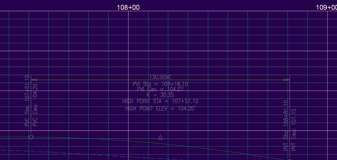
nope. strictly c3d labels. i've attached a picture of each.
Intel(R) Xeon(R) W-2245 CPU @ 3.90GHz 3.91 GHz
64 GB RAM
C3D 2023.2
64 GB RAM
C3D 2023.2
Message 4 of 13
11-09-2016
11:51 AM
- Mark as New
- Bookmark
- Subscribe
- Mute
- Subscribe to RSS Feed
- Permalink
- Report
11-09-2016
11:51 AM
Can you post a sample of this? I've tried to reproduce what you've described and everything seems fine here.
Don Ireland
Engineering Design Technician![]()
If a reply solves your issue, please remember to click on "Accept as Solution". This will help other users looking to solve a similar issue. Thank you.
Please do not send a PM asking for assistance. That's what the forums are for. This allows everyone to benefit from the question asked and the answers given.
Message 5 of 13
11-09-2016
12:20 PM
- Mark as New
- Bookmark
- Subscribe
- Mute
- Subscribe to RSS Feed
- Permalink
- Report
11-09-2016
12:20 PM
C5.0 Plan & Profile is the sheet, P-Site & X-Site are the proposed and existing base drawings. changing the scale in the P-Site drawing affects the profile label in the profile view of the sheet 14 of the C5.0 drawing.
Intel(R) Xeon(R) W-2245 CPU @ 3.90GHz 3.91 GHz
64 GB RAM
C3D 2023.2
64 GB RAM
C3D 2023.2
Message 6 of 13
11-09-2016
05:51 PM
- Mark as New
- Bookmark
- Subscribe
- Mute
- Subscribe to RSS Feed
- Permalink
- Report
11-09-2016
05:51 PM
Sounds like the view port and annotation scale are out of sync. the lower right side of the task bar is a button to sync them
Joe Bouza
Did you find this post helpful? Feel free to Like this post.
Did your question get successfully answered? Then click on the ACCEPT SOLUTION button.
Message 7 of 13
11-10-2016
05:29 AM
- Mark as New
- Bookmark
- Subscribe
- Mute
- Subscribe to RSS Feed
- Permalink
- Report
11-10-2016
05:29 AM
they are synced in my drawing.
Intel(R) Xeon(R) W-2245 CPU @ 3.90GHz 3.91 GHz
64 GB RAM
C3D 2023.2
64 GB RAM
C3D 2023.2
Message 8 of 13
11-10-2016
08:36 AM
- Mark as New
- Bookmark
- Subscribe
- Mute
- Subscribe to RSS Feed
- Permalink
- Report
11-10-2016
08:36 AM
Thanks for that information. Have you tried changing the overall drawing scale in paper space to match the needed viewport scale?
Pat Lowe
Technical Support Specialist
Please click on "Accept as Solution" if post helped you resolve the issue.
Message 9 of 13
11-10-2016
08:43 AM
- Mark as New
- Bookmark
- Subscribe
- Mute
- Subscribe to RSS Feed
- Permalink
- Report
11-10-2016
08:43 AM
that's the problem. invariably the base drawing gets left at 50 scale as most pf my sheets are at 50 scale. however the plan and profile sheets are at 20 scale. the labels should automatically adjust to the 20 scale setting shouldn't they? is there something in the label style that doesn't automatically scale?
Intel(R) Xeon(R) W-2245 CPU @ 3.90GHz 3.91 GHz
64 GB RAM
C3D 2023.2
64 GB RAM
C3D 2023.2
Message 10 of 13
11-10-2016
08:51 AM
- Mark as New
- Bookmark
- Subscribe
- Mute
- Subscribe to RSS Feed
- Permalink
- Report
11-10-2016
08:51 AM
Correct. Here are two ways that will work and one that doesn't:
Works:
1. Create a Data Reference (Short cut) to the alignment and add that to the new drawing. When you do the alignment will pick up the scale of the current drawing. This is the best way to do it
2. Don't label the alignment in the base drawing. In a new drawing create an XREF and then label the alignment through the. This works well for surfaces and for some of the alignment labels.
What Doesn't Work
Xref a drawing with an alignment and have the labels in the xref update
Pat Lowe
Technical Support Specialist
Please click on "Accept as Solution" if post helped you resolve the issue.
Message 11 of 13
11-10-2016
08:57 AM
- Mark as New
- Bookmark
- Subscribe
- Mute
- Subscribe to RSS Feed
- Permalink
- Report
11-10-2016
08:57 AM
but it used to work didn't it? i don't recall ever having this issue before.
Intel(R) Xeon(R) W-2245 CPU @ 3.90GHz 3.91 GHz
64 GB RAM
C3D 2023.2
64 GB RAM
C3D 2023.2
Message 12 of 13
11-10-2016
09:10 AM
- Mark as New
- Bookmark
- Subscribe
- Mute
- Subscribe to RSS Feed
- Permalink
- Report
11-10-2016
09:10 AM
I've always used method #1. I have one file called Civil.dwg per project. This contains all my civil design work. i.e. my proposed surface(s), any corridor work pipe networks profiles etc. No sheets are ever created in this file.
Then I publish via data shortcuts the finished surface, alignments, profiles, pipe networks etc. I'll have a grading plan that references the surface and pipe networks.
Then I'll have my plan and profile sheets that reference them again but also reference the alignments and profiles. I do the same for drainage plan and profiles (profiles of the pipes).
Because it's all data referenced, changes made in the civil file get pushed out to all the other files AND I don't have to worry that turning something on or off (or drawing something needed for my design purposes) will impact my sheets negatively as they only show whatever comes through the data references.
If a reply solves your issue, please remember to click on "Accept as Solution". This will help other users looking to solve a similar issue. Thank you.
Please do not send a PM asking for assistance. That's what the forums are for. This allows everyone to benefit from the question asked and the answers given.
Then I publish via data shortcuts the finished surface, alignments, profiles, pipe networks etc. I'll have a grading plan that references the surface and pipe networks.
Then I'll have my plan and profile sheets that reference them again but also reference the alignments and profiles. I do the same for drainage plan and profiles (profiles of the pipes).
Because it's all data referenced, changes made in the civil file get pushed out to all the other files AND I don't have to worry that turning something on or off (or drawing something needed for my design purposes) will impact my sheets negatively as they only show whatever comes through the data references.
Don Ireland
Engineering Design Technician![]()
If a reply solves your issue, please remember to click on "Accept as Solution". This will help other users looking to solve a similar issue. Thank you.
Please do not send a PM asking for assistance. That's what the forums are for. This allows everyone to benefit from the question asked and the answers given.
Message 13 of 13
11-10-2016
10:31 AM
- Mark as New
- Bookmark
- Subscribe
- Mute
- Subscribe to RSS Feed
- Permalink
- Report
11-10-2016
10:31 AM
This has been a known problem for a bit. The development team has been made aware of it, and hopefully we can get a fix soon.
Pat Lowe
Technical Support Specialist
Please click on "Accept as Solution" if post helped you resolve the issue.
Reply
Topic Options
- Subscribe to RSS Feed
- Mark Topic as New
- Mark Topic as Read
- Float this Topic for Current User
- Bookmark
- Subscribe
- Printer Friendly Page
Forums Links
Can't find what you're looking for? Ask the community or share your knowledge.
Post to forums

