Pressure Networks: Why is the profile top of pipe if insertion point is centerline?

Pressure Networks: Why is the profile top of pipe if insertion point is centerline?

bshaner
Contributor Contributor
1,399 Views
3 Replies
Message 1 of 4

Pressure Networks: Why is the profile top of pipe if insertion point is centerline?

bshaner
Contributor
Contributor

Hi All,


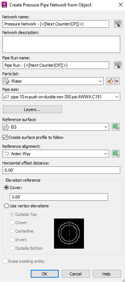
I need help figuring out why my pressure networks are auto-following a profile that follows top of pipe rather than centerline? When creating a pipe run profile it will generate the profile sitting at the top of pipe. I think this is the C3D default, but everything I'm understanding is that the parametric models used by pressure networks have connection/insertion points along the pipe/fitting centerline. Is there a setting to get this auto-generated profile to follow the centerlines? We have many projects with different sizes of pipes and when the profile is forcing the network to snap to top of pipe our tie-ins and areas where pipe sizing changes get really funky, rotating our tees and reducers vertically to try and solve the path.


Thank you!

0 Likes
Accepted solutions (1)
1,400 Views
3 Replies
Replies (3)
Message 2 of 4

lim.wendy
Alumni
Alumni

Hi Brianna,


Welcome to the Civil 3D forum! Thank you for reaching out to the forum. 

To help you with your pressure network, could you tell us a bit more about how you're creating it? For example, are you building it from runs based on an associated alignment and profile?

Also, are you able to share your drawing?


Please let us know if you require further assistance.

If the suggestions helped you, please hit the "Accept Solution" button, as it helps make the solution easier to find for others who might have the same issue. Knowing which topics are solved or not can also help our many users find the questions that still need to be answered. It’s also a great way to say thank you and recognize whoever helped you. 


Wendy Lim

Data Nerd | Community Advocate | AEC Industry


facebook twitter twitter blogs pm


Join the new online Rail Community


Rails Summit


0 Likes
Message 3 of 4

chriscowgill7373
Mentor
Mentor
Accepted solution

The profile is the top of the pipe because that is the way the program was designed to work.  Fittings and appurtenances utilize their center for their elevation coordinates, but when placed in a pipe run, their top is automatically calculated so they are placed in the proper vertical location.  When tying various pipe sizes together, you have to account for this in your profile elevation for the branches coming into the main line.   I agree, that it would be helpful if you could specify what line you wanted to use for the design profile.  The majority of the time, the top of pipe is the most helpful, because we're concerned about the amount of cover on the line.  When we do pipes together, being able to specify the centerline would be helpful, or tying into various process pipes, as they tend to provide their data using the center of the pipe as well.   I would recommend visiting the Civil 3D Ideas forum and if it isnt an idea already, adding it.


Christopher T. Cowgill, P.E.

AutoCAD Certified Professional
Civil 3D Certified Professional
Civil 3D 2026 on Windows 11

Please select the Accept as Solution button if my post solves your issue or answers your question.

Message 4 of 4

bshaner
Contributor
Contributor
This was my fear, it is the way it is because it's the way it is lol, I'm glad there's nothing I'm missing.

For now I'll probably look into custom inputs in the catalog editor to get the results I'm looking for! and add in the idea to the forums!

Thank you!!
0 Likes