Community
- Forums Home
- >
- Civil 3D Community
- >
- Civil 3D Forum
- >
- Re: How do I calculate elevation difference between known points and a surface
Civil 3D Forum
Welcome to Autodesk’s Civil 3D Forums. Share your knowledge, ask questions, and explore popular AutoCAD Civil 3D topics.
Turn on suggestions
Auto-suggest helps you quickly narrow down your search results by suggesting possible matches as you type.
How do I calculate elevation difference between known points and a surface
7 REPLIES 7
SOLVED
Reply
Topic Options
- Subscribe to RSS Feed
- Mark Topic as New
- Mark Topic as Read
- Float this Topic for Current User
- Bookmark
- Subscribe
- Printer Friendly Page
Message 1 of 8
Anonymous
5440 Views, 7 Replies
12-12-2017
08:37 AM
- Mark as New
- Bookmark
- Subscribe
- Mute
- Subscribe to RSS Feed
- Permalink
- Report
12-12-2017
08:37 AM
Hi,
I have been looking through all of the help forums looking for a solution to this and I am struggling to find one.
I am working on a project where we need to work out the amount of fill required across a site to produce a 22 degree overall slope angle while remaining within the site boundaries. The fill is being supported by a retaining wall at the base and this wall will need to be of a variable height to accommodate the fill.
I have survey points for the existing ground level but the elevation for the proposed level is not known as it is governed by slope angle rather than required depth of fill. I have drawn a 22 degree sloping arc around a structure at the top of the slope by extruding a donut shape around it, I could not work out how to have a curved featured with a continuous slope angle without doing so. I need to work out the elevation difference between the points I have and the surface created by the donut. How would I do this?
Once I have the elevation difference, I can work out volumes between the two I believe? I am very new to civil 3D so please be quite specific in your answer!
Any help is hugely appreciated, I have spent a whole day working on this and can't do it when I told my boss I probably could!
Solved! Go to Solution.
Solved by Mike.M.Carlson. Go to Solution.
7 REPLIES 7
Message 2 of 8
12-12-2017
09:19 AM
- Mark as New
- Bookmark
- Subscribe
- Mute
- Subscribe to RSS Feed
- Permalink
- Report
12-12-2017
09:19 AM
If I understand your question correctly, you need to find the volume between your existing and proposed surfaces?
If so- you will need to create a surface using your existing points. Then your second surface would be for your proposed, this could be the tricky part getting the slopes right, hitting the retaining wall, and keeping it all within the project boundary.
Once you have your two surfaces, the cut/fill amount can be calculated by creating a volume surface using the existing and proposed.
Message 3 of 8
12-12-2017
09:43 AM
- Mark as New
- Bookmark
- Subscribe
- Mute
- Subscribe to RSS Feed
- Permalink
- Report
12-12-2017
09:43 AM
Hello-
This is hard to summarize, as there are a lot of steps especially if you're new to Civil 3D, but I will try to help.
Like @jroot recommended, you will first have to create an Existing Ground Surface from the survey points.
Next, I would create a Grading Object that is based on the 22 degree slope first. This will be a reference surface only at the beginning. Create a Feature Line with starting elevations based on the upper most contour shape in your image. This Feature Line will serve as the basis for your Grading Object. The elevation of this Feature Line can/will adjust as you design, but for now, just specify the elevation you started with to create the image.
Then you will create a Grading Object and associated surface with a Grading Criteria that uses "Grade to Distance". This will be created based on %, so you will need to calculate the equivalent % grade from the 22 degree specification (i.e., 40.4%). The distance will be arbitrary, but have it extend past your wall alignment.
Once you have your Grading Object surface, you can apply the Site boundary to this Surface. This will clip the Grading Object Surface to the limits of your Site...make sure this boundary is closed.
Next, you can create a 3rd surface that represents the wall. This surface will also be based on a Feature Line. You will have to create a new Site for this Feature Line called "Wall". It will be based on the starting wall elevation you know of at this stage...I realize this will adjust. Then create a new Grading Object and associated surface based on Grade to Distance criteria. This time you will specify the wall width as the distance with 0% grade to make the top of the wall. Next you will add a "Wall Breakline" to this surface. The wall breakline object can be relative (if you know wall height) or it can be based on elevation. I recommend just setting it to Elevation for right now. Specify an elevation that is lower than you EG surface for now. If you're confused how to apply, search for Wall Breakline in help.
Next I would Create a Alignment and Profile that cuts perpendicular to the existing ground surface, the 22 degree slope Grading Surface, and the Wall grading surface, so you can get a different perspective.
Once you have your Profile View, you can now adjust the upper most Feature Line by selecting it and right clicking "Raise or Lower". The Grading Object will adjust the entire 22 degree slope grading accordingly up or down uniformly. You can also adjust the Wall Feature Line, which will adjust the Wall surface until you get what you want.
I hope this helps.
Michael M. Carlson
Senior Civil Designer
CADD Manager
AutoCAD Civil 3D Professional
AutoCAD Professional![]()
Message 4 of 8
12-12-2017
10:00 AM
- Mark as New
- Bookmark
- Subscribe
- Mute
- Subscribe to RSS Feed
- Permalink
- Report
12-12-2017
10:00 AM
can you elaborate on the donut grading? are you grading at 360 degrees?
Joe Bouza
Did you find this post helpful? Feel free to Like this post.
Did your question get successfully answered? Then click on the ACCEPT SOLUTION button.
Message 5 of 8
12-13-2017
03:59 AM
- Mark as New
- Bookmark
- Subscribe
- Mute
- Subscribe to RSS Feed
- Permalink
- Report
12-13-2017
03:59 AM
Thank you very much for this, I think I have managed to do everything you have said, it was hugely helpful. I have had to break down the wall into sections to adjust each part individually, but that seems to have worked.
Another thing I want to do is create a heat map of where there is too much material over the 22 degree grade and where there is too little so we can show where material needs to be moved from and to. Is there any way that I can do this based on the grade I have drawn prior to adjusting it with the raise/ lower command you said?
Another heat map showing where the toe of the 22 degree slope is higher than the proposed 4m slope and where it is lower would also be useful.
It would be great if you could point me in the right direction with this as well.
Message 6 of 8
12-13-2017
05:54 AM
- Mark as New
- Bookmark
- Subscribe
- Mute
- Subscribe to RSS Feed
- Permalink
- Report
12-13-2017
05:54 AM
Hi-
I am happy I was able to point you in the right direction!
Yes, you can create a TIN volume surface to create that “heat map”. Simply create a new surface, but this time change the Surface type to TIN Volume Surface. Specify your existing ground surface as your “base surface” and the 22 degree surface as the “Proposed surface”. This creates a surface based on the elevation differences between the two surfaces. Right click on this new surface in the Prospector, and choose Build Automatically, so it updates as you make changes to your design. Next, you will assign a style to this volume surface that gives you colored elevation bands that will help you evaluate the material thicknesses in Plan View. This short video will break down the steps to create a style like this:
Here err is another video showing the same kind of surface style approach, but for slope evaluation (in case you need it too):
I hope this helps.
Michael M. Carlson
Senior Civil Designer
CADD Manager
AutoCAD Civil 3D Professional
AutoCAD Professional![]()
Message 7 of 8
12-13-2017
07:14 AM
- Mark as New
- Bookmark
- Subscribe
- Mute
- Subscribe to RSS Feed
- Permalink
- Report
12-13-2017
07:14 AM
Thank you for that, I have managed to make the heat map but it is not draped over the existing topography it is underneath it and in a horizontal plane. This means it is on visible in the correct location when viewing in plan view. Any idea how to fix this?
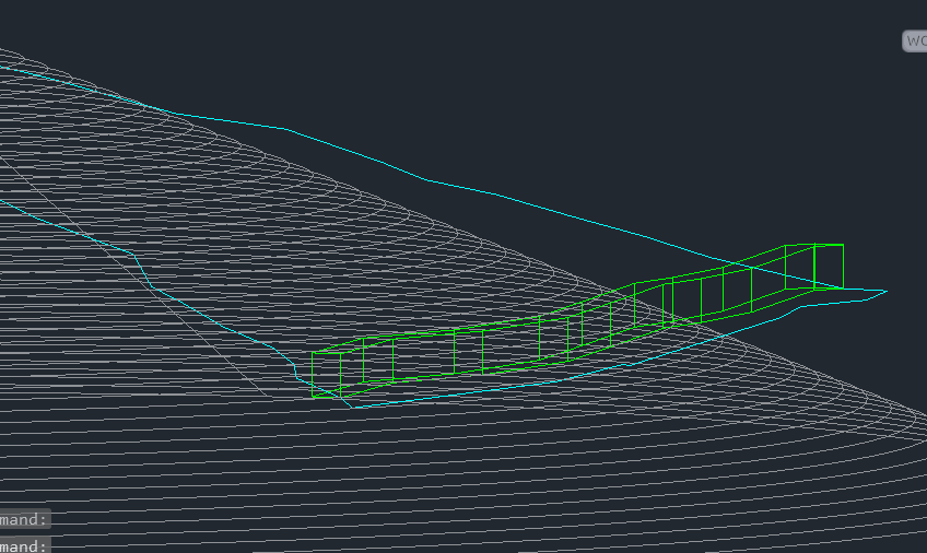
More importantly than this though, I have managed to create a 3D shape out of 3D faces with the perimeter being formed by the intersection of the existing and proposed ground levels. I need to calculate the volume of this shape, how would I do that? I have attached the file so you can see what i mean.
Message 8 of 8
12-13-2017
07:56 AM
- Mark as New
- Bookmark
- Subscribe
- Mute
- Subscribe to RSS Feed
- Permalink
- Report
12-13-2017
07:56 AM
Hi-
Yes that is possible by modifying your surface style you have applied to your TIN Volume Surface. However, it will still show up beneath your EG, if you rotate your View to 3D. This is because the TIN Volume Surface is based on the Elevation Differences not actual elevations.
If you need to edit the style to show the volume surface elevation ranges in 3D, then right click on your volume surface and select Edit Surface Style. Then look for the Analysis Tab along the top of the dialog. Then under Elevations, change the Display type to 3D Faces as shown below:

Final step is to go to the Display tab and change the View Direction to Model and make sure the Elevations Layer is turned on. You need this to view in 3D.

To answer you other question. Yes you can apply a closed boundary to your Volume surface, so that it only shows the volume between the two surfaces compared. I believe I responded to your earlier post with some options to accomplish this.
I hope this helps.
Michael M. Carlson
Senior Civil Designer
CADD Manager
AutoCAD Civil 3D Professional
AutoCAD Professional![]()
Reply
Topic Options
- Subscribe to RSS Feed
- Mark Topic as New
- Mark Topic as Read
- Float this Topic for Current User
- Bookmark
- Subscribe
- Printer Friendly Page
Forums Links
Can't find what you're looking for? Ask the community or share your knowledge.
Post to forums

