Gap between Georeferenced images

Gap between Georeferenced images

Anonymous
Not applicable
3,471 Views
12 Replies
Message 1 of 13

Gap between Georeferenced images

Anonymous
Not applicable

I have inserted images/aerials using MAPIINSERT with georeferenced images obtained from the state mapping portal. I downloaded the TIFF and the associated TWF which are both saved in the same folder. When I insert the images using the World File I get a small gap (~0.5") between the images which shows up in the plot. I tried these same images files in ArcGIS and there is no gap between the images. Any ideas what would cause this to happen? I've attached a screenshot of the gap for reference.


Using Civil 3D 2017.
0 Likes
3,472 Views
12 Replies
Replies (12)
Message 2 of 13

ChicagoLooper
Mentor
Mentor

Your uploaded image shows gray squares, not aerial photos.  If you’re serious about resolving this issue you’ll show the ArcGIS results with images too. 

Chicagolooper

EESignature

0 Likes
Message 3 of 13

kcobabe
Collaborator
Collaborator

Could be the coordinates set in the drawing.  International units versus US Survey units can really mess somethings up.  It's why I always set it by coordinates and set it to match.


R10 - 2020 ACAD
2008 - 2020 Civil 3D
2014 - 2020 Plant 3D
2014 - 2020 Revit
V8i - V8i SS4 Microstation
Infraworks
2018-2020 Inventor
2020 Navisworks
0 Likes
Message 4 of 13

ChicagoLooper
Mentor
Mentor

Unfortunately that is not the case. I frequently bring in geotiff maps referenced to LL83 when modelspace is assigned State Plane. Not only are geotiff maps and modelspace using entirely two different datums but they are using different units as well.  The geotiff maps are 'geographic' and have units of degrees (lat/long) whereas modelspace is 'projected' and has units of feet and despite those differences, the maps are still positioned and orientated correctly when compared against other georeferenced entities already in the map. Even when Bing imagery is brought in as a background, the geotiff map and other entities are all in harmony. The coordinate system for your map doesn't necessarily have to be the same as the coordinate system you assign to modelspace.


The reason this is at all possible, despite what others say or tell you, is because C3D/M3D has the capability to transform from one coordinate system to another and do so on-the-fly. As long as both coordinate system that are being transformed are in the C3D/M3D coordinate system library, then the transformation can, and will, take place. The only exception would be if the two CS's were not applicable to the same area. For example, if you want to transform a CS applicable to California to a CS that's applicable to Florida, you can't do it because they are located in different parts of planet Earth. But if you wanted to transform <UTM84, zone 17N, meters> to <Florida State Plane, East zone, US ft>, you can do that because both CS's are covering or overlapping the same parts of the Earth.

Chicagolooper

EESignature

0 Likes
Message 5 of 13

AllenJessup
Mentor
Mentor

Can you post a link to your state mapping portal and which images you're dealing with? That will help with the diagnosis.

Allen Jessup
CAD Manager - Designer
Did you find this post helpful? Feel free to Like this post.
Did your question get successfully answered? Then click on the ACCEPT SOLUTION button.

EESignature

Message 6 of 13

Anonymous
Not applicable

Thank you all for the responses. To answer the question posed so far. The image attached was the aerials, just zoomed in to show the gap I am talking about. It's large enough that the "lines" from that gap show up on the plots. I've attached the zoom in for ArcGIS for comparison.


The link to where I am pulling the TIFFs and TWFs from is Utah HRO 2012. The metadata for these files states "The georeferenced tiff format of this product is based on the US National Grid 2,000 M x 2,000 M tiles, and is rectified to UTM zone 12 coordinate system NAD83(CORS96) (GEOID09) meters using auto-correlated DEM or LiDAR DEM where available." I set the drawings settings to use the Utah State Planes; NAD83 datum, Central Zone, Meter (UT83-C) coordinate system and I confirmed that the aerials I want are in the central state plane.


And still having problems. What's interesting is that today I am now getting the images to overlap instead of having a gap. Which is the same problem just the other way now. I've tried changing to every single different available CS in CAD and I get the same problem. 


This project is setup in Civil 3D 2017 but I tried it in 2018 with the same results. 


0 Likes
Message 7 of 13

ChicagoLooper
Mentor
Mentor

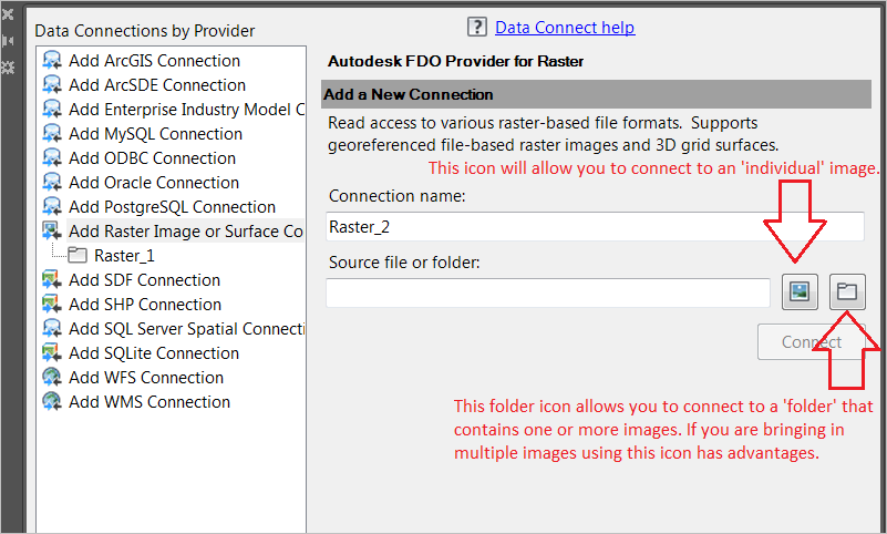
Have you used the Data Connect palette? Using the MAPIINSERT command may not be the appropriate work flow to get your images correctly positioned and oriented in modelspace. Using an FDO connection will give you better results, especially when bringing in multiple images that are adjacent to one another.


1-Using Data Connect palette, connect to the folder that contains all your images.1-Using Data Connect palette, connect to the folder that contains all your images.2-When you connect to the image folder, you'll have options that are NOT available when using MAPIINSERT.2-When you connect to the image folder, you'll have options that are NOT available when using MAPIINSERT. 

Chicagolooper

EESignature

0 Likes
Message 8 of 13

Anonymous
Not applicable

That was actually how I originally brought in the aerials was as a Data Connection. And yes they work great. But they are difficult to work with as far as image adjustments (such as fading for plotting) and drawing order management. 

0 Likes
Message 9 of 13

ChicagoLooper
Mentor
Mentor

Both fading for plotting AND drawing order are STILL controllable using a Data Connection. You just have to know how. Abandoning the Data Connection for those reasons is like saying, "I know how to do that and there may be advantages but I don't want those advantages." 

Chicagolooper

EESignature

0 Likes
Message 10 of 13

ChicagoLooper
Mentor
Mentor

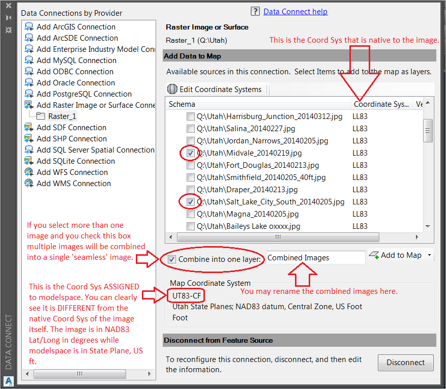
Two adjacent maps from Utah HRO 2012, left and right, without a seam. The two images were combined into a single layer and named to 'My_Utah_Images.' The combined image has no seam. The FADE has been arbitrarily adjusted and set to 25. The default fade is 0, which is no fade at all. The max fade is 50 which will make the image completely white. Bing Hybrid is shown in the background. If I wanted to turn it into B&W instead of keeping it as a color photo I could've did that too.

1-Adjacent images combined & Bing imagery.1-Adjacent images combined & Bing imagery.2-The Data Connect looks like this.2-The Data Connect looks like this.

Chicagolooper

EESignature

0 Likes
Message 11 of 13

Anonymous
Not applicable

@ChicagoLooper wrote:

Both fading for plotting AND drawing order are STILL controllable using a Data Connection. You just have to know how. Abandoning the Data Connection for those reasons is like saying, "I know how to do that and there may be advantages but I don't want those advantages." 


Honestly I've never had luck with getting fading to work through styling the data connection. Brightness and contrast work fine but fading doesn't; granted the problem may be on my end. I'd also like the ability to adjust the transparency, like you can with images you've inserted on a layer. And as far for draw order, in my experience I've had more troubles getting things to display correctly in the Display Manager than it's worth. Usually what seems to happen is any Xrefs will "disappear" from the drawing and I have to detach them and xref them all over again to get them to show. For all those reasons I have found working with inserted images easier. Now I may be missing something in working with data connections and the Display Manager but I don't think so.
 

0 Likes
Message 12 of 13

ChicagoLooper
Mentor
Mentor

I agree, you have no luck.


I still cannot reproduce the gap between georeferenced images that you have described in your first post. Even when using the same online site to download images, I can't replicate the gap. If you're getting a gap, then your work flow must be questioned.


Using Data Connect the term FADE makes the image lighter, less saturated. When using MAPIINSERT or ATTACH to insert an image, then the term BRIGHTNESS is the parameter to use to make the image lighter--using FADE instead of brightness will make your image turn gray and is good for making an image with a white background less reflective and easier on the eyes by turning it light gray. As for contrast, I use it for tracing and outlining purposes, especially hand drawn lines on a scanned image, then turn off the image layer once the traced line work is complete. Have not used contrast adjustment for a final deliverable, never.

Chicagolooper

EESignature

0 Likes
Message 13 of 13

Pointdump
Consultant
Consultant

Zapzak,

Try as I might, I cannot find any data to download from your link, which covers the entire state of Utah. Can you zip together and post your specific images?

Oh, and have you tried using Raster Design?

Dave

Dave Stoll
Las Vegas, Nevada

EESignature

64GB DDR4 2400MHz ECC SoDIMM / 1TB SSD
NVIDIA Quadro P5000 16GB
Windows 10 Pro 64 / Civil 3D 2027
0 Likes