Cannot create intersection

Cannot create intersection

ar182
Contributor Contributor
3,518 Views
16 Replies
Message 1 of 17

Cannot create intersection

ar182
Contributor
Contributor

I am having an issue in the attached drawing where it will not let me create an intersection when I select the intersection point.


I am sure this is a simple fix however I cannot seem to resolve the issue. Any help would be much appreciated.


Thanks

0 Likes
3,519 Views
16 Replies
Replies (16)
Message 2 of 17

Jeew-m
Mentor
Mentor

Hi,

As I know Civil 3D intersections are created when two roads crosses. In your case it is the same road.

So you have 3 options. 

Create a separate alignment and go with automatic intersection

Use single alignment and go with manual intersection method

Use connected alignment option with single alignment


Thanks


Jeewana Meegahage
Design Engineer
Autodesk Civil 3D Tutorials
Facebook | YouTube | LinkedIn


0 Likes
Message 3 of 17

ar182
Contributor
Contributor

@Jeew-m Thanks, I wasn't aware of this.

0 Likes
Message 4 of 17

ocastaneda
Advocate
Advocate

You have only one alignment. Here is a decent video showing the workflow for using this tool. 


https://www.youtube.com/watch?v=3Cp0qXR-aug


Try to recreate the intersecting alignment as a second alignment and define a connection point between those 2 depending on the needs of your design. 


hope this helps bud!!!, 


If you find this answer helpful please click the ACCEPT solution and/or if you like my answer please click on the LIKE icon... 


Oscar Castaneda

Transportation Designer / P.E.


0 Likes
Message 5 of 17

ar182
Contributor
Contributor

@Jeew-m Trying to do this with connected alignments however the RHS alignment has to be connected onto itself which Civil 3D will not allow.


Is there another way to do this?

0 Likes
Message 6 of 17

ar182
Contributor
Contributor

I have managed to do the attached with feature lines.


Any time I create a junction when I go to the section editor it always looks wrong.


Can someone have a look at the drawing and let me know their thoughts please?

0 Likes
Message 7 of 17

ar182
Contributor
Contributor

Is anyone able to help out with this?


Thanks

0 Likes
Message 8 of 17

Jeew-m
Mentor
Mentor

Well can you follow this method.

Create a new corridor. For this corridor you stations range would be 330 to End.

Create a corridor surface for this corridor.

Create a new alignment using create alignment from existing alignment option only from 330 to end from your main alignment..

Create a surface profile for this new alignment from the corridor you created.

Now you have two alignments and profiles so that you can use the normal intersection wizard.

Thanks


Jeewana Meegahage
Design Engineer
Autodesk Civil 3D Tutorials
Facebook | YouTube | LinkedIn


Message 9 of 17

ocastaneda
Advocate
Advocate

Hey @ar182 


I put this video trying to answer your question here. I hope this helps you if not let me know and I'll try to get back to you soon.


If you find this answer helpful please click the ACCEPT solution and/or if you like my answer please click on the Like icon... 


Oscar Castaneda

Senior Transportation Designer / P.E.

Message 10 of 17

ar182
Contributor
Contributor

@ocastaneda Appreciate the video!


I will give this a go.


Question about the alignments. Will there not be any issues about having "overlapping" alignments.


Did you start the 2nd alignment at a random point (ie this alignment does not need to be that long)


When you create the profile for the 2nd alignment, how you do take exactly the same profile from road 1 to ensure there are no discrepancies and it ties in correctly?


Thanks!

0 Likes
Message 11 of 17

ocastaneda
Advocate
Advocate

Hey happy to help.


Will there not be any issues about having "overlapping" alignments.

There should not be any issues for this purpose. Just be careful and organized managing the data within this model as you continue developing your 3d design. Remember that your corridor will be defined by 2 base lines. 


Did you start the 2nd alignment at a random point (ie this alignment does not need to be that long)

I defined that starting point randomly. You are correct, this doesn't need to be that long. Is your design so you know the limits you can assign depending on your project needs. 


When you create the profile for the 2nd alignment, how you do take exactly the same profile from road 1 to ensure there are no discrepancies and it ties in correctly?

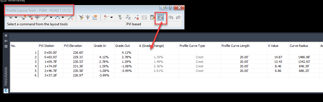
I just copied the station/elevation/curve data from the profile grid view here (see attached image).


Let me know it if works! 


Message 12 of 17

ar182
Contributor
Contributor

@ocastaneda 


Tried to recreate what you explained and I ended up with the attached.


Not sure if the Road 1 alignment is extending itself after I create the junction?

0 Likes
Message 13 of 17

ar182
Contributor
Contributor

Another question regarding the kerb return assembly and alignment.


Which orientation does the assembly need to be ie lane to right or left?


I have watched many videos and there is only ever one kerb return assembly used to create an intersection. When I try and do this my corridor always end up inside out (footpath on inside and road on the outside)?

0 Likes
Message 14 of 17

ocastaneda
Advocate
Advocate

Hi @ar182 


How much experience you have modeling corridors in C3D? The reason I am asking you is to see how can I put something together to show you this. I really never use this intersection tool (other than a quick layout to determine initial impacts), as curb returns have many dependent geometry constrains based on many elements from the main corridor, targets, existing conditions, etc. 


What are you using for your CR profiles? Feature lines or alignments, and are these independent or extracted from the main corridor model and dynamically linked to it? 


I am trying to understand your question and problem better to see how I can provide to you something helpful.


Let me know boss! 

0 Likes
Message 15 of 17

ar182
Contributor
Contributor

I am quite new to Civils 3D but have been watching a lot of videos.


I have successfully and unsuccessfully used the intersection tool and created intersections using connected alignments and feature lines.


If you open the first attachment I posted in this thread you will see I created a junction with one side being a connected alignment and the other being a feature line. This to get over the problem of not being able to create an intersection on the same alignment.


I think that was fairly successful, would you mind having a look? I wasn't too sure because as I was going through the section editor it did not look 100% correct. (Message 6 in this thread)


Thanks again

0 Likes
Message 16 of 17

ar182
Contributor
Contributor

Can someone have a look at the attached and let me know why I cannot see intersection after I have created them?


The intersection symbol appears in the middle however no geometry shows up.

0 Likes
Message 17 of 17

ar182
Contributor
Contributor

Can anyone help with this, really not sure why the intersection is not showing up.


Even when I use the wizard in a new drawing all that generates are 2 offset alignments for one road, really confused.

0 Likes