UNRESOLVED: Inlet/outlet geometry not allowing transfer of flow URGENT HELP

UNRESOLVED: Inlet/outlet geometry not allowing transfer of flow URGENT HELP

Anonymous
Not applicable
9,855 Views
52 Replies
Message 1 of 53

UNRESOLVED: Inlet/outlet geometry not allowing transfer of flow URGENT HELP

Anonymous
Not applicable

Dear Autodesk Help.


In regards to my last post (this is becoming very urgent as I have tried multiple different ways) I rebuilt my Inventor model to first extrude holes for the inlets, and then extrude solids to mark the inlets. In CFD, when highlighting using volumes, these inlets are highlighted as one volume. The flow is still contained in this volume when the model is run. I have attached my latest inventor and CFX files, as well as another print screen of what i am experiencing in this model.


Assistance would be much appreciated, as I am going the same way as described and found previously and have no idea why this fluid isn't crossing over.


Kind Regards,


JAck

0 Likes
9,856 Views
52 Replies
Replies (52)
Message 41 of 53

Xiaojin.Zhang
Autodesk Support
Autodesk Support

Hi Jack,

After you have teavviwer installed on you home computer, could you please send me the ID and password by the private message so we can connect to you?

Thank you!


Xiaojin Zhang
Message 42 of 53

Anonymous
Not applicable

Shall do Xiao thank you,


Regards,


Jack

0 Likes
Message 43 of 53

Anonymous
Not applicable

Hi Guys,


Just uploading the latest model and a screenshot of it's result: 


This is the best result I have got so far, in this instance I supplied volume flow rates through the side outlets, I had a positive pressure at the two side ramps, positive pressure for the inner 3 extrusions, and a P= 0 outlet among these extrusions to allow the model to balance itself for mass conservation.


also added some temperatures and activated natural convection and gravity. Should my inlets with a Volume flow/scalar also include a temperature? or will that be over constrained on an inlet? 


The scale is at 50 ppm, noted that changing the scale down still shows very high values of scalar for the bottom area, still - a much better result than what I have been achieving.


Please see attached,


Regards,


Jack 

0 Likes
Message 44 of 53

Anonymous
Not applicable

Hi again,


Attached latest model that produced the best results so far, although there was very high ppm CO right near the CO outlets, but nowhere else - a better result. This is using volume flows in/out and having 2 p=0 ramps to allow the system to balance.


Kind regards,


Jack

0 Likes
Message 45 of 53

Jon.Wilde
Alumni
Alumni

Hi Jack,


We are looking into this here also so do not feel that you need to run models there.


Your numbers are not the same as what we discussed on the phone, you have 60,000 l/s moving through the model now, is that the final figure that we should be using?

Please do confirm this as we were using 46,400 l/s after we spoke.


I also need to comment on some of your boundary conditions:

Simply, all inlets need Scalar, Temperature and either a Flow or Pressure Condition.

All outlets need either a P=0 or a Flow Rate.


Your ramps must be pulling air in, 3000 l/s each based on the other boundary conditions but they have no Temp or Scalar. They do need these values for CFD to know how to initialise things.

The outlets should not have a Temperature or Scalar assigned. Please remove the Temperature conditions, the air would likely be a different value to this as we are adding heat to the model and CFD needs to calculate that itself.


The side and underside inlets all look OK to me though 🙂


I took a step back to see what is causing issues and ran without natural convection and scalars, which was interesting as it ran really smoothly with no recirculation over any P=0's. Now I am adding each back in to see which might be causing us issues.


Could you confirm what flow figures we need to be using again?

Is it what we spoke about or what you now have assigned in your latest model?


Thanks,

Jon

0 Likes
Message 46 of 53

Anonymous
Not applicable

Hi John, 


I was originally using 93000/2  (46 500) for exhaust and 73 000/2 (36 500).


The latest model I sent was me increasing the flow rates by arbitrary values to see if it would help get more of the CO out of the system, as using flow rates and pressure reliefs seemed to be giving me somewhat promising results - sorry to confuse you with that one!


I will assign only a flow rate out of the model now, and see how that goes with two P = 0 relief outlets.


When you removed the convection and other stuff, were you still seeing a high scalar result?


Hopefully speak tonight mate! 


Regards,


Jack


0 Likes
Message 47 of 53

Anonymous
Not applicable

Hi Guys,


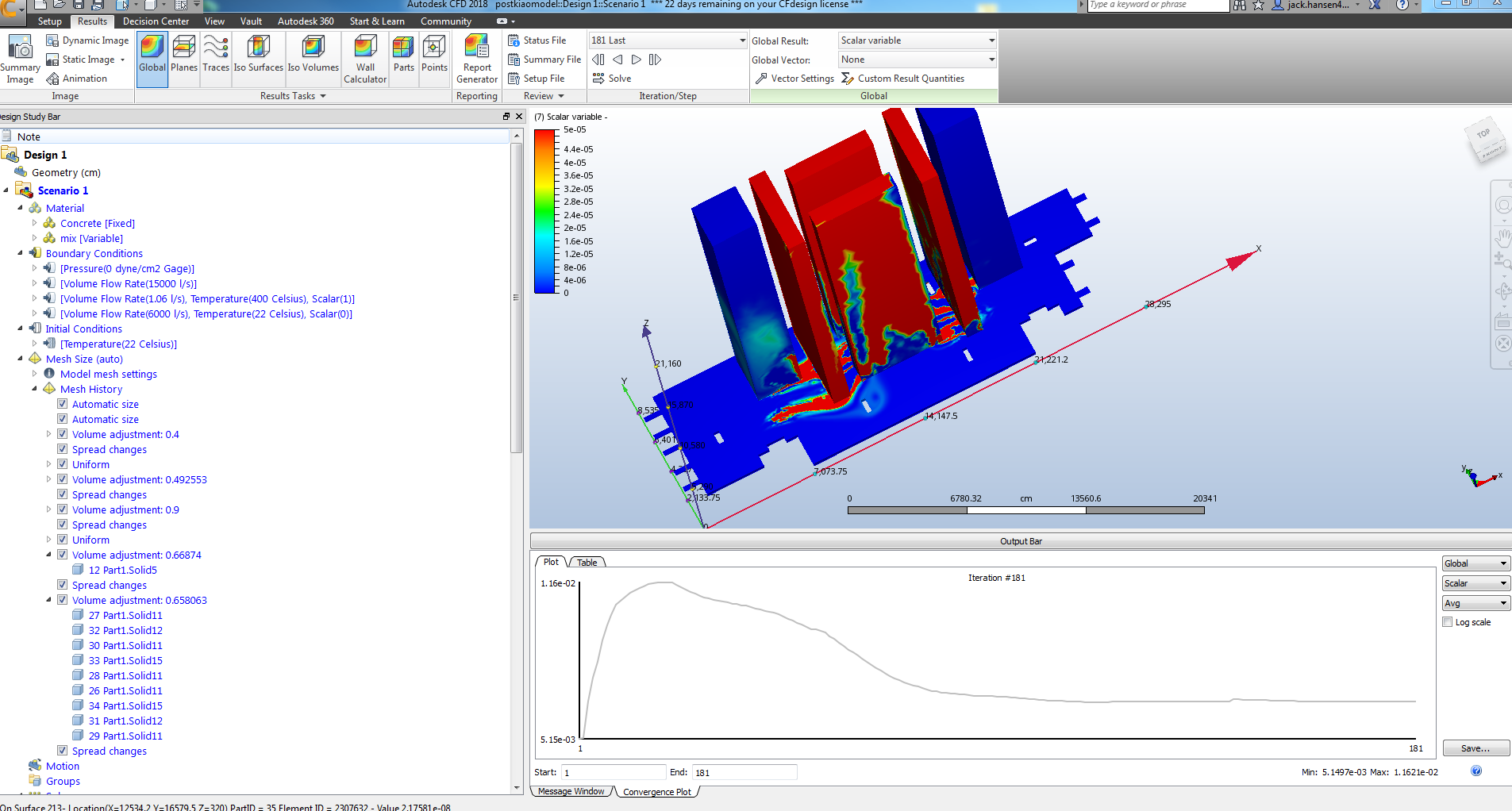
Thought i'd just put up my latest run: It is definitely the best result in terms of keeping the CO lower, although there are still areas that have up to .01 scalar which is obviously far too high! 


This model I used higher airflow to see if that would change the amount exhausted, I believe it does,


- 37M elements


- only took 181 iterations to fully converge.


Attached model and screenshot, 


Regards,


Jack


0 Likes
Message 48 of 53

Xiaojin.Zhang
Autodesk Support
Autodesk Support

Hi Jack,

Thank  you for letting us know your progress. I am so happy to see that you got a better result.

Actually, I did some testing on the model you originally sent to us. I am also thinking about increasing the supply air flow to dilute the CO concentration.

Below is my velocity result.

velocity.png

Given the position of the supply entrance and the volume flow rate, there are many areas that supply air could not reach to. 

Therefore, we get a high CO concentration in this area. So my thought is to increase the supply air flowrate or change the supply air entrance to somewhere which can help mixing like shown in picture below. 

scalar.png


Please let me know my thoughts. Also attached my model for your reference.

Thank you!


Xiaojin Zhang
0 Likes
Message 49 of 53

Anonymous
Not applicable

Hi XiaoJin,


Thank you for your input, you got a result quite similar to mine.


In regards to the airflow supplied to the bottom of the car park - I see that it would help distribution if there was some air applied from the bottom of the area. I will  have to check with the technical manager on what I can do with this. I may rebuild the model slightly with perhaps different sized openings for the airflow inlets, outlets and carbon monoxide outlets.


There isn't a way to set the required scalar value inside the car park, and thus allowing the model to solve for a specific airflow at the inlets? Just to gauge what sort of number the model comes up with.


Have you heard from Jon lately? Would also be good to hear his feedback. Shall continue on.


Regards,


Jack 


0 Likes
Message 50 of 53

Xiaojin.Zhang
Autodesk Support
Autodesk Support

Hi Jack,

It is possible to set a scalar boundary condition inside the model. Like the link below:

https://knowledge.autodesk.com/support/cfd/learn-explore/caas/sfdcarticles/sfdcarticles/How-to-set-u...

But flow boundary condition is not allowed to be applied inside the model. So you can't set the CO volume flowrate.

Though I am not familiar with carpark design. I don't think the model has a good air exchange system according the velocity distribution.

So, I would suggest to rebuild the model if possible.


PS. I believe Jon is still running your model now and will let you know his thoughts soon.

Thank you!


Xiaojin Zhang
0 Likes
Message 51 of 53

Anonymous
Not applicable

Hi Xiao,


After having a look at the smoke visibility page, I am thinking perhaps I should model the CO outlets differently - with the outer barrier that comes out past the end of the outlet so the flow can only go in one direction, do you think this is necessary?


I understand about the flow distribution, still though, if you were to imagine only 2L/s going into a big box, no matter where about, and then big outlets that are pulling 40 000 L/s out, you'd expect to see everything getting sucked out! especially considering both are gases and are going to diffuse in all directions automatically.


I will see what I can change with the model to see if it will make significant difference. I have to check whether I am limited in my design in regards to having outlets down the bottom (this will require larger duct runs and wouldn't be preferable to the client.


Please also see for yourself and Jon - I am attaching a result for a test box I made using the same values - this still showed a high level of CO in the corner of the box, which was too high - Seeing this I'm a little bit unsure which way to move forward. Note this hasn't full converged yet!


No worries, Thank him for working on it!


Regards,


Jack


0 Likes
Message 52 of 53

Xiaojin.Zhang
Autodesk Support
Autodesk Support

Hi Jack,

I understand below what you said: 


I understand about the flow distribution, still though, if you were to imagine only 2L/s going into a big box, no matter where about, and then big outlets that are pulling 40 000 L/s out, you'd expect to see everything getting sucked out! especially considering both are gases and are going to diffuse in all directions automatically.


However, my thought is if CO is  pulled out by the exhaust without mixing with the supply air, CO will keep the high concentration on its trajectory.

(Please keeping in mind that CO keeps ejecting in your model)

I don't think it is necessary to change the CO outlet. If it  is possible to change the location of supply air entrance, exhaust or the ramp, I would  try that first.

I hope my reply makes some sense.

Thank you!


Xiaojin Zhang
0 Likes
Message 53 of 53

Anonymous
Not applicable

Hi Xiao,


I see what you mean how it builds up in certain areas that effectively become dead spots, still not sure if this would happen or it would get sucked out regardless!


I am having a look at my actual dimensions now. I think that the areas that the CO is pumped from should be much smaller (total of 6m^2).


 and that I should have much more area for my inlet grilles, and perhaps make the exhaust grilles slightly smaller - to account for what it will be roughly sized to in reality to keep in more consistent, do you think this would make much difference? I will do this anyways, shall probably have the new model up by tomorrow, as I am leaving the office quite soon!


Shall keep having a look, haven't been able to see my supervisor to ask about blowing air north from the bottom of the model! cheers for your input Xiao!


Regards,


Jack 

0 Likes