Community
Bifrost Forum
Welcome to the Bifrost Forum. This is the place for artists using Bifrost to ask and answer questions, browse popular topics, and share knowledge about creating effects procedurally using Bifrost.
You can also visit the Bifrost Community on AREA to download an array of ready-to-use graphs, read Bifrost news and updates, and find the latest tutorials.
Turn on suggestions
Auto-suggest helps you quickly narrow down your search results by suggesting possible matches as you type.
Reply
Topic Options
- Subscribe to RSS Feed
- Mark Topic as New
- Mark Topic as Read
- Float this Topic for Current User
- Bookmark
- Subscribe
- Printer Friendly Page
Message 1 of 22
03-17-2021
02:14 PM
- Mark as New
- Bookmark
- Subscribe
- Mute
- Subscribe to RSS Feed
- Permalink
- Report
03-17-2021
02:14 PM
emitting combustion properties
Hi,
I'm learning the workflow for bifrost combustion and I've found something that doesn't seem to work as expected. When emitting voxel properties during an active simulation, the fuel emission appears delayed by one frame. For example, if I want to inject voxel_fuel_methane values into my simulation at frame 3, it appears that those values don't actually appear until frame 4 and in-fact don't appear to react to temperature until frame 5. Perhaps I'm misunderstanding how the combustion model in bifrost works, but it appears if I want my explosions to happen at specific frames I have to account for a delay in when the reactants are actually accounted for in the simulation. I don't see this behavior when I'm injecting voxel_fog_density or voxel_temperature. If the source_air node has an arbitrary start frame fog_density and temperature properties are injected at those start frames. Substeps don't appear to have any effect on this phenomena. I have attached a scene file for reference.
Thanks in advance for you assistance.
21 REPLIES 21
Message 2 of 22
03-18-2021
02:45 AM
- Mark as New
- Bookmark
- Subscribe
- Mute
- Subscribe to RSS Feed
- Permalink
- Report
03-18-2021
02:45 AM
Hi,
Thanks for reporting this issue. It looks like a bug related to the start and end frame when having multiple sources -- we will look into it.
I have attached a scene file with a single source that does not have a delay.
In some cases there can be a bit of delay if the burn rate is too low meaning that we have fuel rich conditions and the oxygen needs to diffuse a bit into the fuel for anything to start happening, but that doesn't seem to be the case here.
FYI, to inject detail into combustion simulations (like e.g. seen here https://youtu.be/mnFAGtaODig?t=247) the rebel pack has a collection of influence fields such as the pyroclastic influence (which was used for the example in the link above), and the einstein influence.
Cheers,
Michael
Michael Nielsen
Principal Engineer

Maya 2020.4 marks a major milestone for visual programming in Bifrost for Maya. With a focus on bringing richer, procedural workflows to more areas of your pipeline, we've added powerful scattering, instancing, volumetrics, and FX capabilities to Bifrost. Learn more: autode.sk/2K4jdRJ
Message 3 of 22
03-18-2021
09:48 AM
- Mark as New
- Bookmark
- Subscribe
- Mute
- Subscribe to RSS Feed
- Permalink
- Report
03-18-2021
09:48 AM
Glad to confirm it's a bug. This brings up another question. While I can emit voxel_fuel_methane (and other types) from the same source_air node as my voxel_fog_density and voxel_temperature, I can't vary fuel amounts per point. Or at least I haven't found a way to do that. The vary_source_property node only changes the ignition_temperature of the fuel. To be more clear. The scene file I provided is a very simple scene set up, I'm sourcing from a much more complex source. It's something very similar to the pyro_burst_source in Houdini. I don't want all my source geometry to emit fuel. Currently all points contribute an equal amount and stamp fuel with the same oxygen percentage and burn rates. I would like to be able to tell the source input that some points shouldn't contribute to the fuel source or even better that I can vary the amount of fuel per point.
Thanks for sharing the tips on detail. I'm actually already aware of methods to inject detail into aero simulations. I omitted them from this file as to make it as clean as possible to demonstrate the problem.
Message 4 of 22
03-19-2021
04:43 AM
- Mark as New
- Bookmark
- Subscribe
- Mute
- Subscribe to RSS Feed
- Permalink
- Report
03-19-2021
04:43 AM
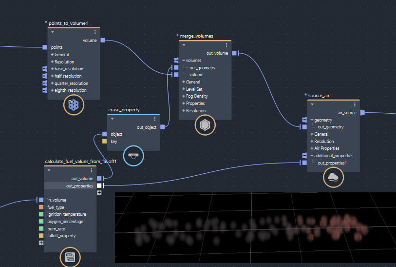
You're right, the vary_source_property node currently doesn't support variation per point for burn rate and oxygen percentage. However, I have made a new compound called vary_source_fuel and example scene file attached to this post that will allow you to vary burn rate and oxygen percentage per point. As you can see from the attached image, the vary_source_fuel compound takes as input an arbitrary field for the burn rate and the oxygen percentage along with an input volume.
You can dive into vary_source_fuel to see how it works and also add variation for other properties by following the same approach and naming conventions.
Cheers,
Michael
Michael Nielsen
Principal Engineer
Message 5 of 22
03-19-2021
08:00 AM
- Mark as New
- Bookmark
- Subscribe
- Mute
- Subscribe to RSS Feed
- Permalink
- Report
03-19-2021
08:00 AM
FYI, some users experienced a problem with the scene file attached above. I have fixed these issues in the scene file attached here.
Cheers,
Michael
Michael Nielsen
Principal Engineer
Message 6 of 22
03-19-2021
09:39 AM
- Mark as New
- Bookmark
- Subscribe
- Mute
- Subscribe to RSS Feed
- Permalink
- Report
03-19-2021
09:39 AM
Excellent! Thanks Michael. I'll check this out. Do you mind if I keep this thread open to ask other questions I might have in regards to the aero combustion model?
Message 7 of 22
03-19-2021
01:32 PM
- Mark as New
- Bookmark
- Subscribe
- Mute
- Subscribe to RSS Feed
- Permalink
- Report
03-19-2021
01:32 PM
I've looked into this file. It doesn't exactly do what I was hoping. There is a variation of fuel properties, but it appears that the combustion doesn't work correctly. The voxel_fuel_methane, voxel_gas_oxygen and voxel_gas_nitrogen properties are stamped over the entire simulation every evaluation. Any change that the simulation makes in them is immediately overwritten by the source. This might be because fuel values are blended in to simulation by directly setting voxels rather than adding or pulling values. I noticed the source_fuel node has a "fuel_mode" property that is not directly user accessible and that is missing from the vary_fuel_source compound you've created. Although, digging into the simulator it appears that the combustion expects the fuel_mode to be of a "set" value anyway. So I'm not sure how much that matters. Further complicating this, based on what I understand of the simulator, the nitrogen and oxygen act as percentages. So it doesn't exactly make sense to just "add" them over time but obviously we don't just want to reseed their values every time step. What we really want is the ability to inject units of fuel in specific locations and vary the amount of fuel injected over time. The simulator should either assume the standard atmosphere oxidizer ratio or the user should be able to adjust that via the combustion settings rather than burden the source with that information. Though the source should probably be able to specify how much of the oxidizer is diffused into the fuel.
I also noticed that you've voxelized your inputs rather than letting the simulator do that work. I tried building a similar compound that just sets point_* values for each of the combustion elements (point_fuel_methane, point_gas_oxygen, point_gas_nitrogen), but it appears those values or either ignored or overwritten by a source_fuel node. I also don't quite understand why we'd use a signed distance field vs fog volume in this case. To expand on that, I have quite a bit of experience with Houdini Pyro which uses fog volumes as it's input sources. An SDF would just tell me distance from a surface, but maybe I don't quite understand the nuances of BiFrost volumes.
Message 8 of 22
03-22-2021
05:28 AM
- Mark as New
- Bookmark
- Subscribe
- Mute
- Subscribe to RSS Feed
- Permalink
- Report
03-22-2021
05:28 AM
Sure, feel free to keep this thread open for further discussion.
The source only stamps voxel_fuel_methane, voxel_gas_oxygen and voxel_gas_nitrogen inside the source itself, not in the entire domain. You can verify this with the attached scene file where I have placed a second fuel source that does not ignite and the fuel inside that remains constant. However, the combustion system itself does normalize the mass fractions of all the gases (fuel, oxygen, nitrogen etc) to sum to 1. That could explain what you're seeing (unless there's a bug in the version you're using).
You're right that values inside the source are being set/stamped into the domain. You can use any mode you like: add, set, max etc, but the combustion system will again normalize them in order to be able to perform physics based combustion calculations. The motivation behind using the set mode by default is that the source acts as an area where the pre-mixed fuel and oxidizer enters the simulation in its pure form. This is similar to how in the real world pre-mixed fuel enters a combustion chamber in pure form after which it ignites and mixes. Furthermore it allows us to emit a given mixture of fuel and oxidizer in an area and then have a flame propagate through it.
I understand the confusion our representation of oxygen, fuel etc can lead to. Particularly if you're used to and know the details of the combustion models used in other packages where typically you can add any amount of fuel which will then burn at some linear rate producing heat under the assumption that enough oxygen is always present.
In Bifrost we adopted a physics-based combustion model. The goal is that you would not necessarily need to know
anything about how we represent fuel, oxygen etc internally. Rather, using the burn rate and oxygen percentage
parameters, you can specify any mixture of fuel and oxidizer that can possibly exist in the real world. In particular the burn rate lets you specify from fuel rich flames in the range [0;1) over stoichiometric conditions at 1 to lean flames in the range (1;2], see image here https://en.wikipedia.org/wiki/Premixed_flame#/media/File:Bunsen_burner_flame_types.jpg
The oxygen percentage determines the fraction of oxygen in the oxidizer. So with an oxygen fraction at roughly 0.2 the oxidizer would be air, and at 1 it would be pure oxygen. With a burn rate at 1 and oxygen percentage at 1 you get the hottest most explosive flame.
With the compound I provided you can vary burn rate and oxygen percentage in time and space so it should be possible to inject more fuel at specific locations and vary it over time. If you can't model the effect you're trying to achieve with this setup, please let us know what's missing.
Sorry that the voxelization up front led to confusion. I have made a new version that performs the voxelization inside instead. The solver itself can take a mesh, signed distance or fog volume as inputs, but for the compound I made I needed the signed distance in order to know where to evaluate the fields that determine the burn rate and oxygen percentage. The core solver cannot at the moment evaluate fields directly during emission.
Using fields to evaluate the burn rate and oxygen percentage has the advantage that these can vary arbitrarily throughout the volume of the source. If on the other hand you specify the burn rate and oxygen percentage
per vertex of the input mesh they can only vary along the surface and are then extrapolated into the volume of the source so the variation of these inside the source volume will be more uniform.
I have however extended the vary_source_fuel compound and attached to this post such that you can also vary the burn rate and oxygen percentage per vertex on the mesh. In particular, if the mesh being input to the vary_source_fuel has properties point_burn_rate and point_oxygen_percentage it will just use those properties and compute the equivalent fuel, oxygen and nitrogen percentages. If the input mesh has no such properties, it will
use the input burn rate and oxygen percentage fields to vary the fuel, oxygen and nitrogen. There's no need for a subsequent source_fuel node: as you have already noticed, the source_fuel will overwrite some of the varying properties.
Cheers,
Michael
Michael Nielsen
Principal Engineer
Message 9 of 22
03-22-2021
06:17 PM
- Mark as New
- Bookmark
- Subscribe
- Mute
- Subscribe to RSS Feed
- Permalink
- Report
03-22-2021
06:17 PM
Oh man, thanks for setting this up @michael_nielsen
It does help explain how BiFrost does combustion. If I understand correctly, the compute_mass_factions node does the work of equalizing the amount of fuel to oxygen to nitrogen ratios. Basically a fuel/oxidizer mixture. If I want part of an object to contribute to the fuel injection, I need to reduce the burn_rate and oxygen_fraction on those points. So I can set the maximum burn rate and oxidizer amounts for my combustion and then scale those off using a falloff property. I've chopped up the compound you've created to focus more on the parts that I'm trying to control.
I think I might have encountered another bug. They way I would like to emit aero is from points. It seems like they way the combustion properties are built is inconsistent when voxelization sizes are changed. It appears that when the geo_detail_size shrinks, the combustion gets much more violent. Also when the Fluid_Detail_Size increase the combustion also violently explodes. If I use geometry with faces and vertices I don't get this reaction, but if I scatter points across the same surface, I get this inconsistency.
It seems that using points to emit density and temperature work as expected, but when applying combustion properties I get an unexpected result. This could also be the result of me not understanding all the parts of applying the custom properties.
In addition to this query, I have some questions about the setup that you've put together. I noticed you've placed an additional compute_mass_fractions node outside the iterate loop. I'm not sure the purpose of this as it's not used in the loop as far as I can tell. I'm asking because sometimes BiFrost is able to read data from parts of the graph that aren't directly connected (EG voxel_proxy_fields). In the set properties nodes you have a double underscore after the property name (EG, "point_gas_oxygen__") pardon my ignorance, but what does that do? I'm not familiar as to why that would be necessary. I'm also a little confused as to when one should use a "set_property" node over a "set_geo_property" node. The documentation for "set_property" basically just says "don't use this", but it clearly does something important related to simulation. It would be nice to have some clarification as to what that is exactly so I could more effectively leverage it.
Thanks,
Chris
Message 10 of 22
03-23-2021
06:05 AM
- Mark as New
- Bookmark
- Subscribe
- Mute
- Subscribe to RSS Feed
- Permalink
- Report
03-23-2021
06:05 AM
Hi Chris,
No problem.
Note that the user-facing oxygen percentage does not need to be lowered if you want more fuel. It just controls the amount of nitrogen vs oxygen in the oxidizer, and the internal fuel and oxidizer percentages are determined solely by the burn rate.
Thanks for reporting the bug with the emission from points. I looked at the volume and it looks like huge fuel fractions are showing up probably due to a bug in the conversion of point properties to volume. We will look into that. In the meantime I think a way to work around this would be to do the conversion of the points to a volume yourself and then compute the mass fractions on the volume instead to bypass the internal conversion of points to volume. Similar to how the compound I sent to you allows you to iterate over the volume.
Regarding your other questions:
- The extra call to compute_mass_fractions is due to an internal bug and we will get that fixed. But right now compute_mass_fractions needs to be pulled outside of the loop. In fact, you will need to modify your scene file as showed in the attached image to avoid a crash when re-starting maya.
- The double underscore is part of the internal naming scheme and signals to the system that the property is spatially varying. Note that this was not really intended to be user-facing so it's not that intuitive.
- set_property vs set_geo_property: set_property should be used if you just want to set a property like a named float etc on your object. I'll check if the docs need to change. Thanks for pointing this out. set_geo_property should be used if you want to set a spatially varying point, face or volume property that is linked to some geometric object's topology.
Cheers,
Michael
Michael Nielsen
Principal Engineer
Message 11 of 22
03-24-2021
06:36 PM
- Mark as New
- Bookmark
- Subscribe
- Mute
- Subscribe to RSS Feed
- Permalink
- Report
03-24-2021
06:36 PM
Hi Michael,
Thanks for taking the time to explain how the combustion system in BiFrost works in more detail. From how I understand it, the idea of the fuel source was for the user to specify a type of fuel and the source would handle the mass of that fuel. Then using the oxygen percentage and burn rate, you'd control how the fuel burned and the solver would combust that using it's physically based modeling. I think I get what is going on with fuel sources in that if I input a geometry, the volume has a "density" based on the type of fuel I select. If I want less fuel, I need to source an object the is physically smaller as there's no real control to diffuse the fuel. I kinda thought that's what oxygen percentage is supposed to do, but it doesn't seem to do that in a way that I can find to give myself practical control of combustion. Which makes sense, as even with oxygen percentage of zero the fuel can still mix with the air around it and combust, as what I really want is to just not have fuel.
From a practical user stand point, was the intention to have the user input fuel as a separate source (which is currently bugged) or was the fuel designed to be combined with the source air when source voxel_fog_density and voxel_temperature?
Back my real dilemma. I've adapted the files you've generously provided, however, I'm still coming up with an issue when it comes to continuous emission. If I emit in a single frame, the combustion reacts as I expect, however, when I emit over multiple frames, combustion doesn't happen. Or at least it seems to me that the solver and the source are fighting for control. As it seems to me that the source is just resetting values inside itself and any combustion that the solver tries to do gets overwritten.
I've also found that this source doesn't play nice with array inputs into the source_air. I have to use a volume_merge to combine my voxel_fog_density beforehand rather than just inputting that directly into the source_air node.
You'll see in my file that I've cut a couple things out of the compound. I noticed your compound used the SDF to do a bit of masking of values, but removing that didn't seem to have any effect the combustion model in both continuous emission (which doesn't work correctly) or single frame (which does). My intuition says that this might be a problem with volumetric emission. For example, if I make a voxel_fog_density volume and my source_air node "sets" density. I don't get a simulation, because all the voxel data that is zero also is set. So my voxel_fog_density gets advected and then when the source is called again, the entire simulation is covered by the volume which effecting erases all the simulation that happened. Which is why when sourcing voxel_fog_density, one uses rate or add or max. Unless, this was not the intended function of set. I think the same thing is happening with voxel_gas_oxygen, voxel_gas_nitrogen, and voxel_fuel_*. The custom volume from the emitter sets those values on ever step effectively killing and simulation that was done on the previous step.
Message 12 of 22
03-24-2021
10:36 PM
- Mark as New
- Bookmark
- Subscribe
- Mute
- Subscribe to RSS Feed
- Permalink
- Report
03-24-2021
10:36 PM
Hi Chris,
Thanks for all the feedback.
Which version of Bifrost are you using? If I play your scene file in Bifrost 2.2.1.1 I get the result you see in the attached image with continuous emission and I don't see any immediate problems. If there's too little volume expansion happening, try adjusting the expansion scale on the aero combustion settings. I have attached an updated version that does not require the merge volumes, just in case. If you input a volume as geometry to the source air node it must have either a voxel_fog_density or a voxel_signed_distance. If it doesn't have such a property it could be that it emits over the entire domain and that explains what you're seeing with values getting overridden, and could also explain the problem you were seeing with array inputs to the source. If you believe this is not the case, please send us scene files to repro.
In order to have fuel to vary across the plane you could leave the oxygen percentage fixed, but just let the burn rate vary from 1 (all fuel will react with oxidizer) at the end where you want the most burning towards 2 (no fuel at all) at the end where no burning should happen. In that case you might need to switch the soot generation model from advanced to simple to see the soot because not as much soot is emitted in the real world when the flame is lean (burn rate above 1).
You're right about the masking with SDF values, it's not strictly necessary because the volumes voxel_fog_density or voxel_signed_distance will determine where properties are emitted.
Regarding one vs multiple sources, the intent was that you could do both approaches. You often get the most realistic results if you use two separate sources for ignition and fuel because continuously emitting and igniting in the same place can generate too high temperatures.
Cheers,
Michael
Michael Nielsen
Principal Engineer
Message 13 of 22
03-25-2021
10:12 AM
- Mark as New
- Bookmark
- Subscribe
- Mute
- Subscribe to RSS Feed
- Permalink
- Report
03-25-2021
10:12 AM
Hi Micheal,
I'm running BiFrost 2.2.1.0. However, the result from your screen shot is exactly what I'm seeing when I run the simulation. What I'm seeing that's different is when I only emit on a single frame. The expansion and temperature are drastically different. I tried increasing expansion like you've suggested, but that didn't produce a result that came close to the single frame emission. It looks like the expansion forces happen, but only end up pushing voxel_fog_density around. It's not until I get to an expansion value of "8" that I started to see temperature and fuel getting kicked out of the emission area, but at that value the fluid expands wildly. I wouldn't expect that if running a continuous emission of fuel properties that I'd need to drastically adjust simulation parameters. All the screen shots are captured from the file I sent. The fuel_varation_from_volume2.ma file produces the same result.
Message 14 of 22
03-25-2021
10:36 AM
- Mark as New
- Bookmark
- Subscribe
- Mute
- Subscribe to RSS Feed
- Permalink
- Report
03-25-2021
10:36 AM
Hi Michael,
I'm making a second post because I can't attach more than 3 images to a single post. I think I'm miscommunication my intention with sourcing separate values for fog_density and combustion sourcing. I've saved an image to show my graph and a screen shot of what the source looks like in the viewport for each configuration. It's only when I merge the volumes together to combustion properties get emitted. If I rely on the aero solver to mix the source volumes, I don't get the same result. I would like to specify which parts of my source emit properties into the aero solver. This seems pretty straight forward with voxel_fog_density and voxel_temperature, but it appears fuel is handled differently. From how you've described it, the source_fuel node just adds combustion properties and the solver internally computes and emits those inside of and SDF or fog_density defined by the source. I still suspect that trying to inject specific spatially adaptive values into the combustion solve causing it to function erratically because it wasn't designed to handle that functionality.
Thanks,
Chris
Message 15 of 22
03-26-2021
03:52 AM
- Mark as New
- Bookmark
- Subscribe
- Mute
- Subscribe to RSS Feed
- Permalink
- Report
03-26-2021
03:52 AM
Hi Chris,
Thanks so much for the screen shots and additional explanation. It makes perfect sense now.
First of all, I would recommend that you switch to Bifrost version 2.2.1.1 as it has some additional bug fixes.
Secondly, I can confirm that there appears to be a bug with multiple inputs to the source when one of the inputs does not have a fuel property. We will look into that. The merge volumes workaround you came up with appears to suffice as a workaround for the time being though until we get that bug fixed.
The issue with less burning with continuous emission vs single frame emission also makes sense. I have attached a scene file that has a better and consistent more behavior. What I changed was:
(1) The oxygen percentage is constant for the emitted fuel-mixture.
(2) The burn rate goes from 2 where falloff is 0, to 1 where falloff is 1. This means that where falloff is 1 we have perfect combustion and where falloff is 0, there's no fuel.
(3) Continuously setting the temperature overrides the temperature produced by the combustion. So instead of setting the temperature I use the max mode. The max mode smears the emission region a bit so I had to increase the temperature slightly to get ignition.
(4) On the combustion settings node I switched to the simple soot generation model, otherwise you won't see any soot generated from the combustion, because when burn rate is between 1 and 2 all fuel is burned and no soot is produced (this is like in the real world where you get just a blue flame). In Bifrost you can also visualize the water vapor and blue flame (see e.g. here https://www.youtube.com/watch?v=a09PWcbYbjw).
The reason for the inconsistent behavior between single frame and continuous emission does indeed have to do with setting the fuel properties as you have pointed out. When the burn rate is low (in your case 0.05) fuel is emitted with very little oxidizer so for the single frame emission, oxygen would diffuse into the fuel, burning it and creating a higher temperature. Whereas for the continuous emission, we would continuously override the oxygen diffusion thus creating less burning. We will need to discuss this a bit internally. The problem occurs because the setup is non-physical in the sense that burning and fuel injection is happening in the same location which doesn't occur in the real world. However, for graphics the setup does make sense. In the meantime I hope you can use the modified setup I provided in the attached scene file.
Cheers,
Michael
Michael Nielsen
Principal Engineer
Message 16 of 22
03-26-2021
04:28 AM
- Mark as New
- Bookmark
- Subscribe
- Mute
- Subscribe to RSS Feed
- Permalink
- Report
03-26-2021
04:28 AM
Btw, note that to actually see the voxel_fog_density you emit directly from the fog volume, you might have to increase the fog density property on the points to volume node or change the rendering parameters.
Cheers,
Michael
Michael Nielsen
Principal Engineer
Message 17 of 22
04-07-2021
12:33 AM
- Mark as New
- Bookmark
- Subscribe
- Mute
- Subscribe to RSS Feed
- Permalink
- Report
04-07-2021
12:33 AM
Hi Chris,
Were you able to move forward with your combustion simulations or did you end up being blocked by the issues you reported?
As we were fixing some of the issues you reported a few other things became clear:
(1) When the burn rate goes from 1 to 2 it's actually better to turn oxygen diffusion off because the mixture already contains oxygen and is highly explosive (I've attached an updated scene file, see also attached image).
(2) The default value for fuel was set to 580, should be zero (see attached image).
(3) In your original scene file, the main cause for the difference in the look between single frame vs continuous emission actually seemed to be due to the set mode on temperature (and not so much set mode on oxygen and fuel) which overwrote the temperature result from the combustion. The attached scene file uses max mode.
Cheers,
Michael
Michael Nielsen
Principal Engineer
Message 18 of 22
04-07-2021
11:31 AM
- Mark as New
- Bookmark
- Subscribe
- Mute
- Subscribe to RSS Feed
- Permalink
- Report
04-07-2021
11:31 AM
Hi Michael,
Apologies for the radio silence, my attention has been divided a bit in the past couple of weeks. I've been re-evaluating how I want to emit fuel in my combustion simulations. Mostly just trying to figure out exactly what the solver is expecting and trying to work inside those constraints. I believe I have a pretty good handle on oxygen percentage and burn rates and how they affect the fuel. One control that I would like to see is a fuel mass. As we've discussed, there isn't a linear relationship between fuel and temperature like there is in other solvers. However, it appears when a source in voxelized, the interior is converted to 100% fuel with the aforementioned combustion properties. The difficulty arises when the user wants to input less fuel. The way to do that currently is to make the source physically smaller so that the the fuel takes up less volume. This has a problem when it comes to resolution. Basically my fuel amount becomes tied to the resolution of my simulation as I can easily end up with fuel sources that are less than one voxel in size. EG: a simulation that has a large explosion and small residual fires. BiFrost does allow for sources to have different sized voxels and it will simulate those in the same solver, however most of the time I don't need (or have time to simulate) the amount of detail required to create very tiny fuel emissions. A cheat the would be used in other solvers is to lower the amount of fuel emitted, but BiFrost doesn't currently support that workflow. I assume we are modeling fuel as a vapor, it should be possible to emit a more diffuse fuel into the voxels. Although I may be misunderstanding how physical combustion works. (I didn't major in chemistry 😉 It seems way to easy in BiFrost to emit too much fuel for a given situation. If I coated a piece of metal with gasoline, it doesn't explode, but I'm not sure exactly how to imitate that in BiFrost. Gasoline isn't a fuel type that is modeled, but also as far as I can tell, I'd have to use a voxel scale that would accurately represent the amount of fuel that I'd expect to combust. Which as we know, smaller voxels sizes with lots of velocity mean more substeps further increasing the simulation times. Would like to know your thoughts on this.
Thanks,
Chris
Message 19 of 22
04-08-2021
02:44 AM
- Mark as New
- Bookmark
- Subscribe
- Mute
- Subscribe to RSS Feed
- Permalink
- Report
04-08-2021
02:44 AM
Hi Chris,
Thanks for your reply and no worries about the radio silence. I just wanted to make sure that if you are blocked we understand why such that we can improve the solvers and workflow moving forward.
Your idea about fuel mass makes perfect sense. It is true that with the standard source_fuel setup the same amount of fuel+oxidizer is seeded everywhere inside the source uniformly. However, internally we do represent fuel via its mass fraction which can vary both between voxels and inside a single voxel, so it should already be possible to vary the amount of fuel without having to make the source physically smaller. I have modified and attached the example scene file to illustrate this. See also attached images. In the example the burn rate varies from one end to the other giving rise to different amounts of fuel, burning and volume expansion/explosion. There are 4 example settings.
However, it might be that this example doesn't capture the effect you're after? For example, currently it's not possible to vary the expansion scale spatially in case you wanted to add more explosive volume expansion effects only in certain areas.
For simulating something like metal coated in burning gasoline I would suggest to look at the example attached and determine which type of flame you are after. Then set the burn rate accordingly. To prevent the coating from exploding initially you could set expansion scale to zero. We don't have a correct model for gasoline but propane is often used for practical special effects and might be used instead. If this doesn't help solve the issue and if it's not too time-consuming it would be a great help if you were able to share a scene file illustrating the issue.
Cheers,
Michael
Michael Nielsen
Principal Engineer
Message 20 of 22
04-23-2021
12:52 AM
- Mark as New
- Bookmark
- Subscribe
- Mute
- Subscribe to RSS Feed
- Permalink
- Report
04-23-2021
12:52 AM
Hi Chris,
Just wanted to let you know that we tracked down the cause of the issue you were seeing with combustion not working properly with two source inputs and having to use merge volumes instead.
The issue is arising because both source inputs have a fuel property and a fuel mode of SET, and one of the sources has a fuel property of zero. With the SET mode the fuel emitted then depends on the order of the source inputs since they overlap.
There are two ways to fix it:
(1) Swap the order of the inputs on the source air node.
(2) Use the MAX mode instead of the SET mode for fuel (see attached image).
FYI we're working on improving the usability of sourcing to avoid issues like this.
Cheers,
Michael
Michael Nielsen
Principal Engineer
Reply
Topic Options
- Subscribe to RSS Feed
- Mark Topic as New
- Mark Topic as Read
- Float this Topic for Current User
- Bookmark
- Subscribe
- Printer Friendly Page
Forums Links
Can't find what you're looking for? Ask the community or share your knowledge.
Post to forums

