Community
AutoCAD Forum
Turn on suggestions
Auto-suggest helps you quickly narrow down your search results by suggesting possible matches as you type.
Reply
Topic Options
- Subscribe to RSS Feed
- Mark Topic as New
- Mark Topic as Read
- Float this Topic for Current User
- Bookmark
- Subscribe
- Printer Friendly Page
Message 1 of 10
Anonymous
8049 Views, 9 Replies
11-23-2019
05:39 PM
- Mark as New
- Bookmark
- Subscribe
- Mute
- Subscribe to RSS Feed
- Permalink
- Report
11-23-2019
05:39 PM
I am trying to export my design to pdf or jpg to physically print out, but since the design is so small (the smallest features are 25 micron circles), the pdf and jpg conversions do not give me a high-enough quality rendering to use well (e.g. 50 micron gaps are filled in). I tried changing DPI settings to various high numbers (2400, 4800, 9600) under PDF options when I try to export under "DWG to PDF", but it didn't work since the pdf that came out looked the exact same every time.
Solved! Go to Solution.
Solved by woodenlious. Go to Solution.
Solved by Alfred.NESWADBA. Go to Solution.
9 REPLIES 9
Message 2 of 10
11-23-2019
11:02 PM
- Mark as New
- Bookmark
- Subscribe
- Mute
- Subscribe to RSS Feed
- Permalink
- Report
11-23-2019
11:02 PM
how about trying plotter AutoCAD PDF ( High Quality Print ) ?

Imad Habash
Message 3 of 10
11-24-2019
02:25 AM
- Mark as New
- Bookmark
- Subscribe
- Mute
- Subscribe to RSS Feed
- Permalink
- Report
11-24-2019
02:25 AM
Hi,
>> I tried changing DPI settings to various high numbers (2400, 4800, 9600)
>> under PDF options when I try to export under "DWG to PDF", but it didn't
>> work since the pdf that came out looked the exact same every time.
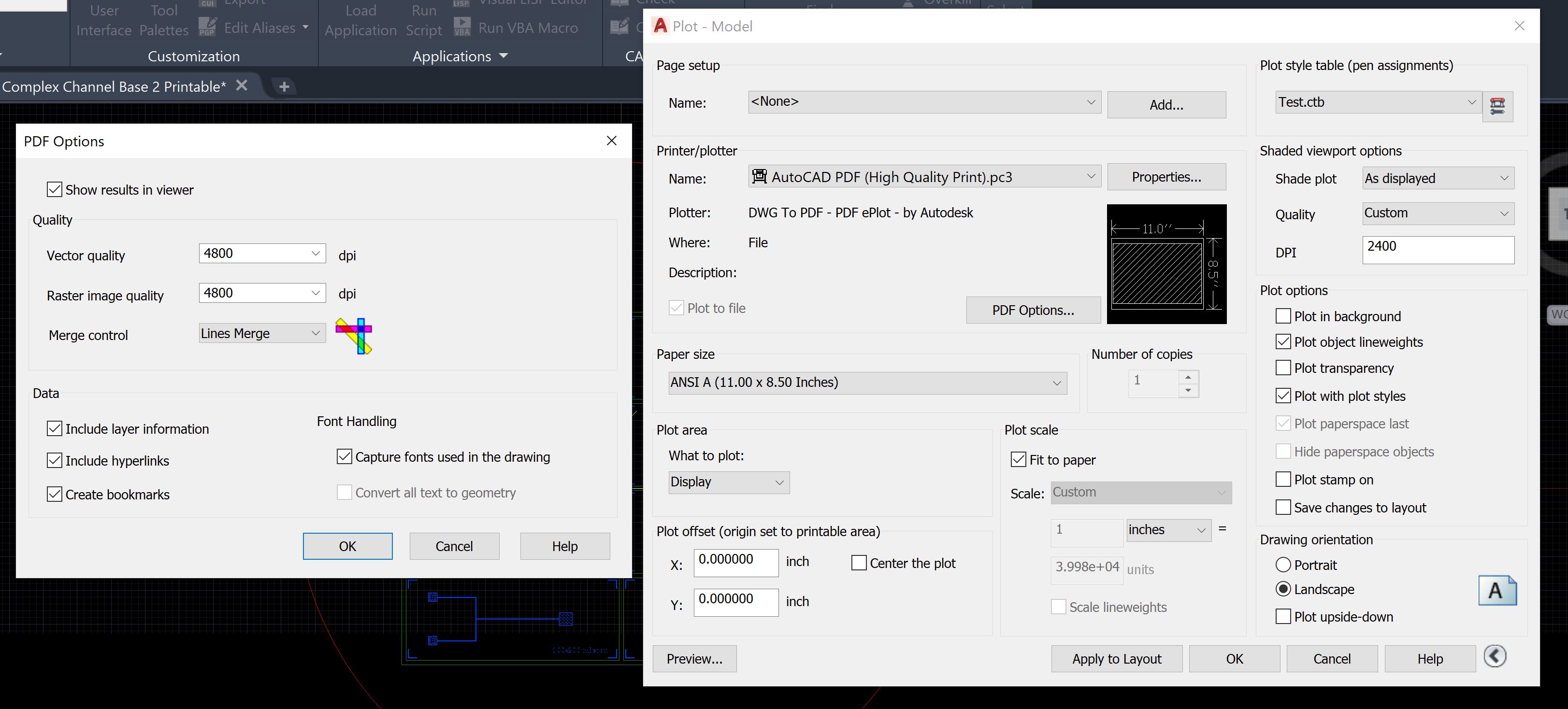
Hey, assuming you are using _PLOT as you are referring to "PDF options" ... how did you set DPI to 9600 ... that is not available in AutoCAD, the maximum resolution is 4800dpi:

Also please show us a PDF (or better 2 PDF's plotted with different resolutions) and describe what is bad with them.
Simply thinking about 4800dpi it's quite difficult to see that on the screen, even zooming in very close.
Just a few tips when quality in PDF's can look lower than expected:
- in the viewports you are plotting (I assume you are plotting from a layout) make sure you have set the visual style to "2D Wireframe"
- in the plot-dialog make sure that "plot transparency" is disabled.
- try to view your PDF's in different viewers just to make sure it's an issue of plotting and not an issue of your viewer.
And just thoughts...maybe I assume something wrong, but lets see:
>> but since the design is so small (the smallest features are 25 micron circles)
Are you expecting to get a PDF that is later used to print 1:1?
Just to verify that ... 25micrometer = 0.025mm ... if that is the diameter of a circle and you need to plot that with a lineweight so the circle is not filled you need to have a lineweight <= 0.008mm (0.0003 Inch) (and even that will show the circle just as square with 9x9 pixel).
So I assume that is not printed for looking to that PDF with eyes, instead the PDF might be used for some type of production and now you should take care of: a PDF does not store vectors with double precision, the circles you get in the PDF are not at the exact position you have them in CAD-X/Y (based on double precision coordinates) and also not with the (double precision calculated) radius. The coordinates of X/Y and R inside a PDF are based on raster values(pixel), accuracy of double precision is definitely lost and so the quality of your small circles too.
I strongly recommend to transfer such objects in a real cad format, not with PDF to your production.
- alfred -
------------------------------------------------------------------------------------
Alfred NESWADBA
ISH-Solutions GmbH / Ingenieur Studio HOLLAUS
www.ish-solutions.at ... blog.ish-solutions.at ... LinkedIn ... CDay 2024
------------------------------------------------------------------------------------

(not an Autodesk consultant)
Alfred NESWADBA
ISH-Solutions GmbH / Ingenieur Studio HOLLAUS
www.ish-solutions.at ... blog.ish-solutions.at ... LinkedIn ... CDay 2024
------------------------------------------------------------------------------------
(not an Autodesk consultant)
Message 4 of 10
11-24-2019
07:53 AM
- Mark as New
- Bookmark
- Subscribe
- Mute
- Subscribe to RSS Feed
- Permalink
- Report
11-24-2019
07:53 AM
Thanks for the replies!
I tried doing the "AutoCAD PDF (High Quality Print)" with 4800 DPI but the quality came out the same as it did for other ones; I'm pretty new to AutoCAD and not exactly fantastic with computers, so I couldn't tell if it was a problem on my PDF end or with the plotting end. I did try the "PublishtoWeb JPG" plotter setting, but the quality was just as bad on a jpg so that made me think it wasn't a pdf problem (although I can't be sure).
I attached the PDFs of when I do the high quality print with 2400 and also 4800 DPI rastor and vector (not sure what those are but I just went for the highest possible), and also a screenshot of what it actually is supposed to look like in AutoCAD. When you zoom in on the PDF, you can't see the channels that are on the close-up screenshot that I took (and yes I am hoping for some kind of 1:1 printable format that I can then send to a printing company like FedEx Printing to print for me).
What do you mean by transferring in a real cad format?
Message 5 of 10
11-24-2019
08:33 AM
- Mark as New
- Bookmark
- Subscribe
- Mute
- Subscribe to RSS Feed
- Permalink
- Report
11-24-2019
08:33 AM
Hi,
>> When you zoom in on the PDF, you can't see the channels that
>> are on the close-up screenshot
Well, your lineweight you used to plot is much too thick, and using small circles, but thick lineweights, is what you get as result.
Can you tell us a bit more about what you are doing then with the PDF's, whatfor are they needed?
- alfred -
------------------------------------------------------------------------------------
Alfred NESWADBA
ISH-Solutions GmbH / Ingenieur Studio HOLLAUS
www.ish-solutions.at ... blog.ish-solutions.at ... LinkedIn ... CDay 2024
------------------------------------------------------------------------------------
(not an Autodesk consultant)
Alfred NESWADBA
ISH-Solutions GmbH / Ingenieur Studio HOLLAUS
www.ish-solutions.at ... blog.ish-solutions.at ... LinkedIn ... CDay 2024
------------------------------------------------------------------------------------
(not an Autodesk consultant)
Message 6 of 10
11-24-2019
09:00 AM
- Mark as New
- Bookmark
- Subscribe
- Mute
- Subscribe to RSS Feed
- Permalink
- Report
11-24-2019
09:00 AM
I am a bit unsure on how to change the line weight; I went into the plot style editor and changed some of the lineweights for a few colors including the colors I used in AutoCAD but it didn't seem to have any effect on the plotted model. The PDFs are just intended for me to have a version of the model of those channels that I can send to a printing company (or print myself on a laserjet). I would want to print it out with a 1:1 ratio on transparency sheets so that the areas inside the rectangular features are transparent, and the areas inside the circles and also outside the rectangles are all dark. I would use this transparency to fabricate channels in the lab of the same dimensions as in my model.
Message 7 of 10
11-24-2019
10:53 AM
- Mark as New
- Bookmark
- Subscribe
- Mute
- Subscribe to RSS Feed
- Permalink
- Report
11-24-2019
10:53 AM
Hi,
>> or print myself on a laserjet
Kidding? You know that your laserjet never supports 4800dpi (or do you have a print shop that has really high end devices?)
>> I went into the plot style editor and changed some of the lineweights
If you do that just as try and error without knowing what you are doing then this most probably fails (sorry for the words, but gaming with the CTB file/settings is the last I would do just to control lineweights).
Don't use CTB or STB at first, start your layermanager and give all layers the lineweight "0.00" which is then the thinnest lineweight possible, then make sure all your objects in the DWG-file have lineweight assigned to "byLayer" and now you are able to plot.
You might upload the DWG-file and I do that for you, just to make sure you have a one-time correct setup.
But I can't make your laser printer printing with 4800dpi. 😉
- alfred -
------------------------------------------------------------------------------------
Alfred NESWADBA
ISH-Solutions GmbH / Ingenieur Studio HOLLAUS
www.ish-solutions.at ... blog.ish-solutions.at ... LinkedIn ... CDay 2024
------------------------------------------------------------------------------------
(not an Autodesk consultant)
Alfred NESWADBA
ISH-Solutions GmbH / Ingenieur Studio HOLLAUS
www.ish-solutions.at ... blog.ish-solutions.at ... LinkedIn ... CDay 2024
------------------------------------------------------------------------------------
(not an Autodesk consultant)
Message 8 of 10
11-24-2019
01:57 PM
- Mark as New
- Bookmark
- Subscribe
- Mute
- Subscribe to RSS Feed
- Permalink
- Report
Message 9 of 10
01-03-2021
08:31 AM
- Mark as New
- Bookmark
- Subscribe
- Mute
- Subscribe to RSS Feed
- Permalink
- Report
01-03-2021
08:31 AM
ME SAME PROBLEM 1 WEEK CANT FIND SOLUTION IMAGE EXPORT VERY BAD QUALITY AS 600X400 OR 3GP EVEN ITS HD RENDER PHOTO DIFFRENT TOTALY THAN AFTER EXPORT AS PDF FROM AUTOCAD -I TRY ALL PLOT SITTING HIGH QUALITY OR MAX DPI AND ALSO ANOTHER EXTERNAL APPS AS NITRO OR CUTE PDF BUT NOTHING WORKS ALL OPTIONS LOOKS FAKE ,WAITING THE SOLLUTION THANKS
Message 10 of 10
04-06-2022
02:51 PM
- Mark as New
- Bookmark
- Subscribe
- Mute
- Subscribe to RSS Feed
- Permalink
- Report
Reply
Topic Options
- Subscribe to RSS Feed
- Mark Topic as New
- Mark Topic as Read
- Float this Topic for Current User
- Bookmark
- Subscribe
- Printer Friendly Page
Forums Links
Can't find what you're looking for? Ask the community or share your knowledge.
Post to forums

