Community
- Forums Home
- >
- AutoCAD Electrical Community
- >
- AutoCAD Electrical Forum
- >
- Re: Network symbols for AutoCAD Electrical?
AutoCAD Electrical Forum
Welcome to Autodesk’s AutoCAD Electrical Forums. Share your knowledge, ask questions, and explore popular AutoCAD Electrical topics.
Turn on suggestions
Auto-suggest helps you quickly narrow down your search results by suggesting possible matches as you type.
Reply
Topic Options
- Subscribe to RSS Feed
- Mark Topic as New
- Mark Topic as Read
- Float this Topic for Current User
- Bookmark
- Subscribe
- Printer Friendly Page
Message 1 of 10
12-11-2020
10:13 AM
- Mark as New
- Bookmark
- Subscribe
- Mute
- Subscribe to RSS Feed
- Permalink
- Report
12-11-2020
10:13 AM
Network symbols for AutoCAD Electrical?
Probably a long shot, but does anybody know of a source for basic network symbold for use with AE?
Like monitors, printers, network switch etc?
9 REPLIES 9
Message 2 of 10
12-11-2020
12:09 PM
- Mark as New
- Bookmark
- Subscribe
- Mute
- Subscribe to RSS Feed
- Permalink
- Report
12-11-2020
12:09 PM
I would draw them like I draw any other symbol.
Here are a couple of examples that I use.
One is an 8 port switch and the other is a Panelview HMI.


Bob Hanrahan
Ace User since 1998
If this answered your question, please click on "Accept Solution"
Message 3 of 10
12-11-2020
12:22 PM
- Mark as New
- Bookmark
- Subscribe
- Mute
- Subscribe to RSS Feed
- Permalink
- Report
12-11-2020
12:22 PM
I don't mean schematic symbols, I'm looking for symbols for in a network layout diagram. Something less involved than a picture but kinda physical.
Message 4 of 10
12-14-2020
06:35 AM
- Mark as New
- Bookmark
- Subscribe
- Mute
- Subscribe to RSS Feed
- Permalink
- Report
12-14-2020
06:35 AM
I use footprint symbols to create my network drawings. I feel like this approach is best, considering the lack of any sort of established library for these and the fact that you never know who's going to be using that drawing in the future....that person might know nothing about networking.
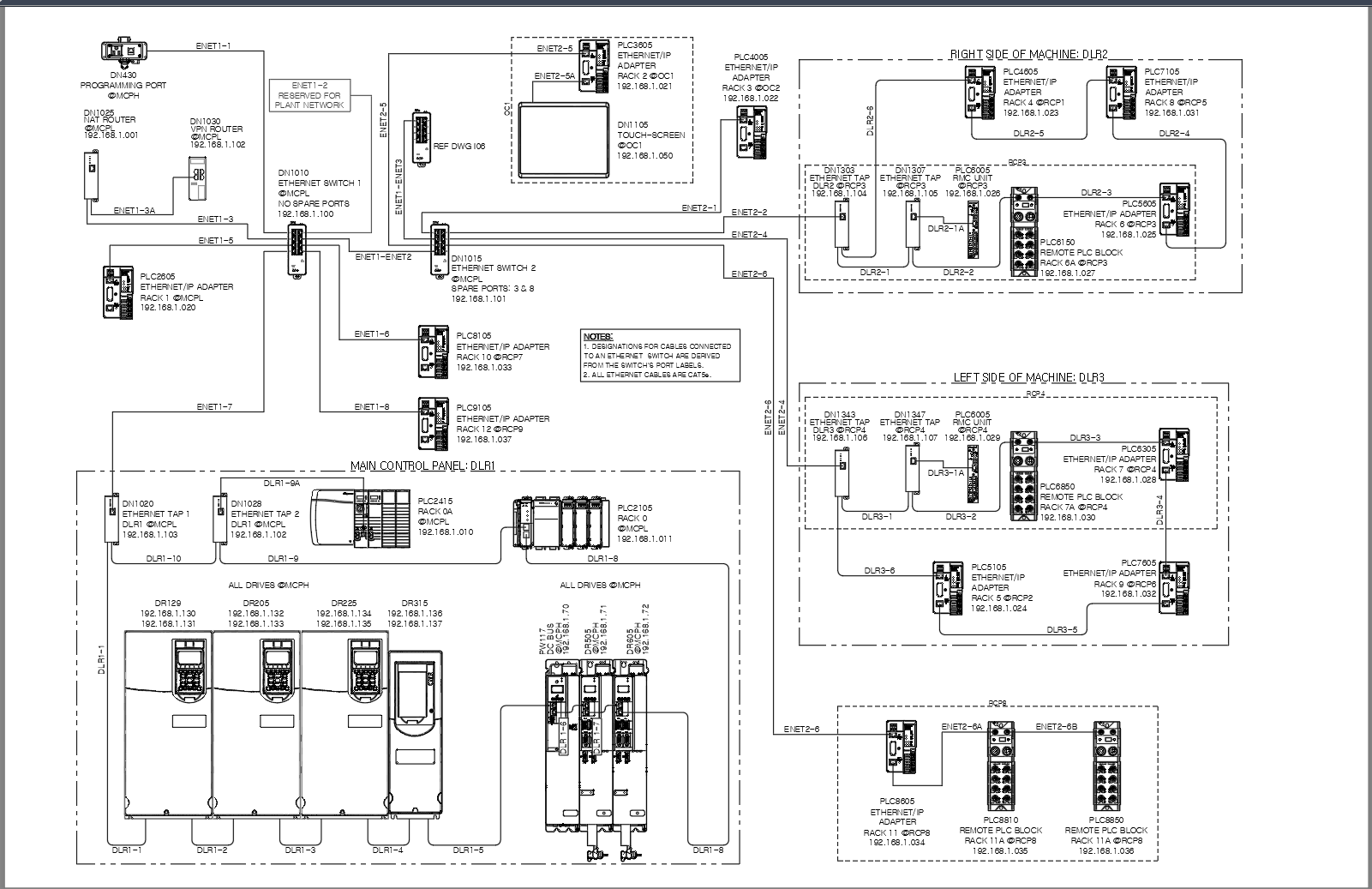
See the attached image, it's a plot preview of one of my network drawings. These symbols are 'dumb' and aren't connected in any way to the schematics or the panel layout. Whenever I can, I plot them out screened, so they appear grey, this is to help the lines depicting the Ethernet cables to pop out more. As for those lines, they are all polylines, just a little extra insurance to keep ACADE from thinking they're wires and putting numbers on them. The symbols are all scaled down by a ridiculous amount so everything fits on an 11x17 plot.
In addition, you'll see that some of the corners on the Ethernet cables are right angles while some are radiused (filleted). The difference is topology: if a device is part of a DLR (Device Level Ring), then I fillet all the corners. Star topology gets right-angle corners. (If we ever use a different topology I guess I'll have to think something else up....one of the problems to deal with when there's no real standard to go by.)
When I draw these, I make every effort to accurately show which ports on the switch the connections are made on, even though this rarely matters. The reason is so we can have a meaningful name for the cables. For star topologies, we name the cables as ENET and add the number of the switch's port they're plugged in to. For ring topologies, we name the cables DLR, and number them sequentially starting at the first one in the ring.
In these examples, annotations are limited to the device tag, device location, and IP address. Sometimes I have to include more; it depends on what the customer is wanting, and/or how we have to integrate into an existing plant network. Both examples are for single machines.
The second example is basically the same as the first but with a larger network with multiple DLR's.
Edit: forgot to attach files
Hope this helps,
Jim Seefeldt
Electrical Engineering Technician
Message 5 of 10
12-14-2020
08:40 AM
- Mark as New
- Bookmark
- Subscribe
- Mute
- Subscribe to RSS Feed
- Permalink
- Report
12-14-2020
08:40 AM
Jim,
I haven't done this but have you thought of using 1-line symbols for the network page? you can then have an association between the components....
I don't worry about "wire numbering" cables because they go on a "No Numbers" wiring layer.
Bob Hanrahan
Ace User since 1998
If this answered your question, please click on "Accept Solution"
Message 6 of 10
12-14-2020
09:56 AM
- Mark as New
- Bookmark
- Subscribe
- Mute
- Subscribe to RSS Feed
- Permalink
- Report
12-14-2020
09:56 AM
I never really thought of that...but also, we don't have a need to maintain an association between the network layout and the schematics. For us, these are really Vanilla drawings, done in ACADE. That's definitely an option to explore, though. Thanks!
Jim Seefeldt
Electrical Engineering Technician
Message 7 of 10
04-12-2022
01:24 AM
- Mark as New
- Bookmark
- Subscribe
- Mute
- Subscribe to RSS Feed
- Permalink
- Report
04-12-2022
01:24 AM
Hi Jim,
very good work! I am wondering if you could share the AutoCAD files for such a project? Sorry I am new to AutoCAD and those example Projects would be very helpful. Thanks in advance
very good work! I am wondering if you could share the AutoCAD files for such a project? Sorry I am new to AutoCAD and those example Projects would be very helpful. Thanks in advance
Message 8 of 10
04-12-2022
07:54 AM
- Mark as New
- Bookmark
- Subscribe
- Mute
- Subscribe to RSS Feed
- Permalink
- Report
04-12-2022
07:54 AM
Sorry, but I moved on from the job where I created those drawings and no longer have access to them.
Jim Seefeldt
Electrical Engineering Technician
Message 9 of 10
02-24-2023
02:18 AM
- Mark as New
- Bookmark
- Subscribe
- Mute
- Subscribe to RSS Feed
- Permalink
- Report
02-24-2023
02:18 AM
Hi,
Came over this searching for network connection blocks (RJ45).
Possible to download these symbols of yours somewhere?
Would be great to get other symbols like HDMI, USB, DP etc. also 🙂
Thanks in adnavce!
Message 10 of 10
02-24-2023
04:45 AM
- Mark as New
- Bookmark
- Subscribe
- Mute
- Subscribe to RSS Feed
- Permalink
- Report
02-24-2023
04:45 AM
Hei Øyvind.
If you just want the symbol as a block, you should search the internet. You can find some here for example:
https://www.cadforum.cz/catalog_en
You have to register to download. Some symbols are 3D only, but it's easy to create a 2D drawing of them using the FLATSHOT command.
Trond Hasse Lie
EPLAN Expert and ex-AutoCAD Electrical user.
Ctrl Alt El
Please select "Accept Solution" if this post answers your question. 'Likes' won't hurt either. 😉
Reply
Topic Options
- Subscribe to RSS Feed
- Mark Topic as New
- Mark Topic as Read
- Float this Topic for Current User
- Bookmark
- Subscribe
- Printer Friendly Page
Forums Links
Can't find what you're looking for? Ask the community or share your knowledge.
Post to forums

