Electric busbars on diagrams

Electric busbars on diagrams

galashkina
Advisor Advisor
6,845 Views
9 Replies
Message 1 of 10

Electric busbars on diagrams

galashkina
Advisor
Advisor

Dear colleagues!

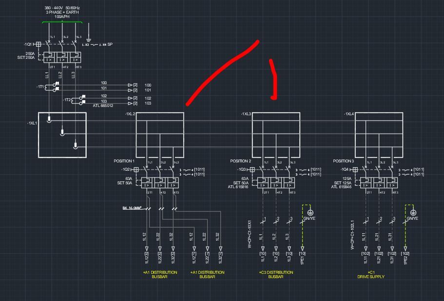
Connections on electrical circuits are created by wires, cables, and metal buses. What AutoCAD Electrical tool do you use to create electrical busbars on a circuit?

I created custom symbols and inserted the bus with the ACONNECTOR command (see the video).


https://knowledge.autodesk.com/ru/support/autocad-electrical/learn-explore/caas/screencast/Main/Deta...


I can use the editing tools for my connector, for example, I can rotate the connector.

However, the "Stretch Connectors" command does not work correctly.

07042021.png 

What can I do to prevent the graphics from deforming when the connector is stretched?

0 Likes
6,846 Views
9 Replies
Replies (9)
Message 2 of 10

galashkina
Advisor
Advisor

Please support my idea of parametric buses

Parametric bus - Autodesk Community

0 Likes
Message 3 of 10

rhesusminus
Mentor
Mentor
I would just draw them as "wires", but with a wire type named "BUSBAR_L1_JUMPER", "BUSBAR_L2_JUMPER" etc. The "JUMPER" keyword will make sure these connections don't appear in the connection report.
Color the wire types in a copperish color, and it'll look good.

Trond Hasse Lie
EPLAN Expert and ex-AutoCAD Electrical user.
Autodesk Expert Elite Alumni
Ctrl Alt El
Please select "Accept Solution" if this post answers your question. 'Likes' won't hurt either. 😉
Message 4 of 10

galashkina
Advisor
Advisor

I also show the tires as wires, but not everyone accepts this buses image in the diagrams.

0 Likes
Message 5 of 10

testsubject
Advisor
Advisor

This is how I did 3 pole distribution blocks (1 in:6out)

testsubject_0-1617822598406.png

I have the WD_JUMPERS attribute to link all the various terminations together.

I put this in the family DB (for Distribution Blocks)


Now, for ground bars, I did it a bit different.

I did these as Parent/Child Groups. Each termination in the bar gets a unique terminal number and them I added the termination in the catalog.

Parent

testsubject_1-1617822862183.png

Child

testsubject_2-1617822977941.png


The Parent is Terminal Lug and then all children get inserted as 1-#. This keeps track of how many connections I have made.


This has been working pretty well for me.


Bob Hanrahan
Ace User since 1998
Autodesk Expert Elite Alumni
If this answered your question, please click on "Accept Solution"
Message 6 of 10

galashkina
Advisor
Advisor

@rhesusminus wrote:
I would just draw them as "wires", but with a wire type named "BUSBAR_L1_JUMPER", "BUSBAR_L2_JUMPER" etc. The "JUMPER" keyword will make sure these connections don't appear in the connection report.
Color the wire types in a copperish color, and it'll look good.

I didn't know that the wires on the jumper layer aren't included in the connection report.

Is it written about this somewhere?

What other layers are not included in the connection report?

0 Likes
Message 7 of 10

galashkina
Advisor
Advisor

Yes, I like this solution.

But right now, electric projects are very complex. There can be several dozen child components. Users don't want to mess around with that much. They want to make a project with the click of a button. ☹️

0 Likes
Message 8 of 10

rhesusminus
Mentor
Mentor

https://knowledge.autodesk.com/support/autocad-electrical/learn-explore/caas/CloudHelp/cloudhelp/201...


2021-04-08_22-16-54.png


To automatically create the project with the push of a button, you need EPLAN 😉


Trond Hasse Lie
EPLAN Expert and ex-AutoCAD Electrical user.
Autodesk Expert Elite Alumni
Ctrl Alt El
Please select "Accept Solution" if this post answers your question. 'Likes' won't hurt either. 😉
Message 9 of 10

galashkina
Advisor
Advisor

Thank you very much!

I need to study this help section carefully. I may have missed something else.

Although it is not specified anywhere that the connections in the Jumper layer are not included in the connection report.

0 Likes
Message 10 of 10

ccad2509
Advisor
Advisor

this how i did it

create symbols for the bus bar carriers and had bus bar wire layers

Capture.JPG