Community
Advance Steel Forum
Welcome to Autodesk’s Advance Steel Forums. Share your knowledge, ask questions, and explore popular Advance Steel topics.
Turn on suggestions
Auto-suggest helps you quickly narrow down your search results by suggesting possible matches as you type.
Reply
Topic Options
- Subscribe to RSS Feed
- Mark Topic as New
- Mark Topic as Read
- Float this Topic for Current User
- Bookmark
- Subscribe
- Printer Friendly Page
Message 1 of 9
01-05-2021
05:55 AM
- Mark as New
- Bookmark
- Subscribe
- Mute
- Subscribe to RSS Feed
- Permalink
- Report
01-05-2021
05:55 AM
Hi guys,
I’m trying to figure out a way of grouping single parts based on their main part Model Role.
Basically all plates that belong to columns on one sheet, those that belong to trusses to another and so on…
At the moment my workflow works like this:
- Select all Column assemblies and number them.
- Do this for all the other model roles separately
- Select all plates that belong to Columns and generate one drawing using DSM for single parts
- Select all beams that belong to Columns and generate one drawing using DSM for single parts
- In the generated drawing, I change the paper size and rearange the generated views.
- I use DPM for assemblies which is fine.
Step 4 takes time that could be spent elsewhere and I’m trying to revise it.
All i would like to see as a result is a set of generated views that are grouped by size (plates by thickness, beams by profile) and by position on the drawing.
I tried adding script to Drawing Process maps for plate thickness, as shown in the attached image. Regardless of the filter working, order of views is not effected by it.
'Check for t=5mm''
Function checkElement(Obj)
checkElement = False
Th = obj.Thickness
If Th = 5 Then
checkElement = True
End If
End Function
Does anyone have an idea how to speed this up?


Easy things are not worth the effort
http://www.teamcad.rs
Solved! Go to Solution.
Solved by Sebastian_Eiche. Go to Solution.
8 REPLIES 8
Message 2 of 9
01-06-2021
01:35 AM
- Mark as New
- Bookmark
- Subscribe
- Mute
- Subscribe to RSS Feed
- Permalink
- Report
01-06-2021
01:35 AM
I think your problem is not so easy to solve as you think.
In your picture, where you show the script (detail style map), you always have the same detail style...so I think you add in every line another script?
This will never work, because the detail style map work in another way.
example: you have to plates in your model, which should be detailed. you select them and start your process. So the process find ithe first plate and have a look in the detail style map for a detail style (mabye found the correct one in line 5), now it take the plate number 2 and also have a look in this detail style map and also found a detail style (maybe line7).
But the process will not sirst select all plates which have the same thickness or something, it "walk" from plate to plate. And because you have 20 lines in your detail style map, the process will always found a correct line.
belonging to your requested result, you had to create not one process with all objects in different lines, what you need is: a process for each requested thickness and then you could create a new suite in the drawing process suite:


So here you had to create a new type for plates:
- process plate 5mm (with the filter for thickness 5mm)
- process plate 6mm ((with the filter for thickness 6mm)
Why don't you just use the exisitng sorting?

Yes I know it will not stop after one thickness, but to move the details to another drawing is maybe a bit faster?
Sebastian Eiche
Application Engineer @Mensch und Maschine acadGraph
If this information was helpful, please use the Accept as Solution function, this make it easier for other users
Message 3 of 9
01-08-2021
03:25 AM
- Mark as New
- Bookmark
- Subscribe
- Mute
- Subscribe to RSS Feed
- Permalink
- Report
Message 4 of 9
01-09-2021
04:13 AM
- Mark as New
- Bookmark
- Subscribe
- Mute
- Subscribe to RSS Feed
- Permalink
- Report
01-09-2021
04:13 AM
Hi, and thx for the suggestions. I actualy tried creating Process Suites, but I ran into another issue when using them in this way. I had to repeat the selection for every plate thickness. If there is a way of setting the selection for all Suites, please let me know. This would make them usable in day to day operations.
I tried Plate thickness ascending, but the SP arent’t in order. Do you know how AS sorts them after plate thickness?
All I’m looking for is that SP (plates) get generated in one drawing, grouped by thickness and sorted by SP mark.
Thx
Easy things are not worth the effort
http://www.teamcad.rs
Message 5 of 9
01-09-2021
05:00 AM
- Mark as New
- Bookmark
- Subscribe
- Mute
- Subscribe to RSS Feed
- Permalink
- Report
01-09-2021
05:00 AM
You need no selection, you need a combination of your scripts which are included in processes. And these processes had to combined in a process Suite.
You create a process for all platesand name it "plates 5mm". And in this process you add you script for thickness 5mm to true. So all other plates will not be detailed.
After this you copy your process and call it plates 6mm, change your script for 6mm thickness =true. Result all you plates with thickness 6mm will be detailed..no other. This you had to do for all your requested thickness. So in the end you will maybe have 20 processes.
Now you change to the process suites and just add all these processes to this suite. By running the suite, the software will now run the first process, then the second ....and so on
Sebastian Eiche
Application Engineer @Mensch und Maschine acadGraph
If this information was helpful, please use the Accept as Solution function, this make it easier for other users
Message 6 of 9
01-09-2021
05:30 AM
- Mark as New
- Bookmark
- Subscribe
- Mute
- Subscribe to RSS Feed
- Permalink
- Report
01-09-2021
05:30 AM
hmm do you search for yourself or for a customer? I think I hat to send you a bill for my tips...=)
So if it's not necessary to have each thickness on a new dwg, you could also create a new process sorting. Therefore you had to open the databases in the Management Tools and open the AstorDetailsBase. There you will find the DetailProcessSort Table. Now you create a new line and define the sorting:
Thickness INC Postion INC.

This could be selected in the process.I have not tested it in a big model, but should work

By using it like this, you don't need scripts, but it will not create a new file for each thickness
Sebastian Eiche
Application Engineer @Mensch und Maschine acadGraph
If this information was helpful, please use the Accept as Solution function, this make it easier for other users
Message 7 of 9
01-09-2021
10:40 AM
- Mark as New
- Bookmark
- Subscribe
- Mute
- Subscribe to RSS Feed
- Permalink
- Report
01-09-2021
10:40 AM
This is exactly what I was looking for. I should know better by now. There is a database for everything in AS.
ps, the previous suggestion with Suites wouldn't work since I need drawings split by model role.
One drawing for all plates that belong to Columns, thickness and position ascending.
One for trusses
One for purlins
...and so on.
This would result in a huge number of proceses combined into multiple Suites. Not practical.
Anyway...
This one is for me
Database tip works perfectly 🙂
Happy new year and holidays Sebastian.
Easy things are not worth the effort
http://www.teamcad.rs
Message 8 of 9
01-09-2021
10:46 AM
- Mark as New
- Bookmark
- Subscribe
- Mute
- Subscribe to RSS Feed
- Permalink
- Report
01-09-2021
10:46 AM
The problem on this database entry is: what happened if an object is changed?
If you work with process suites, there will be a new file for each role-thickness...and so on. So if something is changed, the chance that there's maybe an empty place on these details is big.
So you could create a detail of the changed object and then move it to a detail.
I think the work for producing is in the list cases the better way, because it's more adjustable if something is changing
Sebastian Eiche
Application Engineer @Mensch und Maschine acadGraph
If this information was helpful, please use the Accept as Solution function, this make it easier for other users
Message 9 of 9
01-10-2021
03:39 AM
- Mark as New
- Bookmark
- Subscribe
- Mute
- Subscribe to RSS Feed
- Permalink
- Report
01-10-2021
03:39 AM
I think it’s about what’s easier to manage in the long run (not only in AS) and client standards.
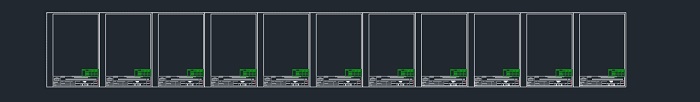
Maybe this will help ilustrate. Here is what my SP prototype looks like. It’s a set of identical A4 papers. I just change the drawing number by adding .n (55.1, 55.2, 55.3…). All SP elements get printed on A4 sizes. It would be a nightmare opening hundereds of SP drawings in search for the rignt one. I’m aware there is Rclick show Single Part detail function, but it dosent compare with having all SP’s in one .dwg. Especialy in the workshop where there is no AS, only ACAD if lucky.
If the element changes, I add nother A4 to the .dwg and a revision indicating the change. It’s usualy a small number of elements, so no problem there.
If you are wondering how is the actual printing done in this case, sometimes on a paper role height 297mm, and sometimes one by one from the actual .dwg.
I have done SP’s in a number of ways.
- One SP per .dwg (A4), with file name same se SP number - Ok for small projects, up to 100 SP’s.
- SP’s by thickness (profile name) on one .dwg (large format) - I didn’t like this one, so I don’t use it anymore. Can’t explaing exactly why.
- Multiple SP’s (that belong to one MP model role) on one .dwg sorted thickness and position - Good for big projects where there is a large volume of similar assemblies needed for production.
- SP’s on Assembly drawings (Process: Selected Assemblies w/ parts - A2 - One per sheet) - Ok for small projects that have low count of similar assemblies. Alsow practical when SP and assemblies are done in different stages (different people). It’s easier and less time consuming for workers in the workshop when putting togeather assemblies with large SP count.
Anyway, thx for all your help, much apreatiated. Instead of sending me the bill, I’d be happy to work it off, if that’s an option XD
Easy things are not worth the effort
http://www.teamcad.rs
Reply
Topic Options
- Subscribe to RSS Feed
- Mark Topic as New
- Mark Topic as Read
- Float this Topic for Current User
- Bookmark
- Subscribe
- Printer Friendly Page
Forums Links
Can't find what you're looking for? Ask the community or share your knowledge.
Post to forums

