Community
Revit MEP Forum
Welcome to Autodesk’s Revit MEP Forums. Share your knowledge, ask questions, and explore popular Revit MEP topics.
Turn on suggestions
Auto-suggest helps you quickly narrow down your search results by suggesting possible matches as you type.
Reply
Topic Options
- Subscribe to RSS Feed
- Mark Topic as New
- Mark Topic as Read
- Float this Topic for Current User
- Bookmark
- Subscribe
- Printer Friendly Page
Message 1 of 5
04-27-2012
12:32 PM
- Mark as New
- Bookmark
- Subscribe
- Mute
- Subscribe to RSS Feed
- Permalink
- Report
04-27-2012
12:32 PM
We finally got a small project in where we are trying to do it completely in Revit. I could have drawn this power plan in about 5 minutes in autocad. in an hour, I have 4 receptacles and a panel placed and I am trying to circuit my receptacles. Do I need to make them a circuit, or can I just draw a wire to each one? Is there a way to edit the wire type (arc, spline, chamfered) so I can somewhat make the wire look the way I want it to? It may be far reaching but could someone show me how their power sheets are looking? We may have to change the look and way we do things, I just want to be able to do it in an easy manner. Any help would be greatly appreciated.
Thanks
Carrie
btw. I have attached a simple power plan to show what I am trying to achieve
Solved! Go to Solution.
Solved by CoreyDaun. Go to Solution.
Solved by CoreyDaun. Go to Solution.
4 REPLIES 4
Message 2 of 5
04-30-2012
06:19 AM
- Mark as New
- Bookmark
- Subscribe
- Mute
- Subscribe to RSS Feed
- Permalink
- Report
04-30-2012
06:19 AM
If you want to be able to Tag the devices with a Circuit Number and create a Panel Schedule, then yes, you have to create Electrical Circuits. Wiring is a separate entity, and is really an intelligent annotation family. Regardless of the load, you can manually control the number of Wires in the form of Tick Marks. In order to Tag a Wire more detailed info, (i.e. Panel, Voltage, Circuits), it mist belong to an Electrical Circuit, which is automatic when connected to an Electrical Device. Simply drawing Wires does not create Electrical Circuits.
There are two ways to draw Wiring: Automatic and Manual. Automatic will quickly generate automatic Wiring once an Electrical Circuits is created. Hover over an Electrical Component with the cursor, press TAB once, and then click to select the "phantom" wiring. Click one of the two buttons in the Ribbon or one of the little icons that appear beside it to convert this wiring into "real" wiring.
Wires can also be drawn manually using the Types listed in the Home Tab of the Ribbon. Segments of Wire from the Automatic layout can be deleted and redrawn manually as desired. Wire can be converted between Types with a setting under properties, which will allow you to change chamfered into arc wiring or vice versa.
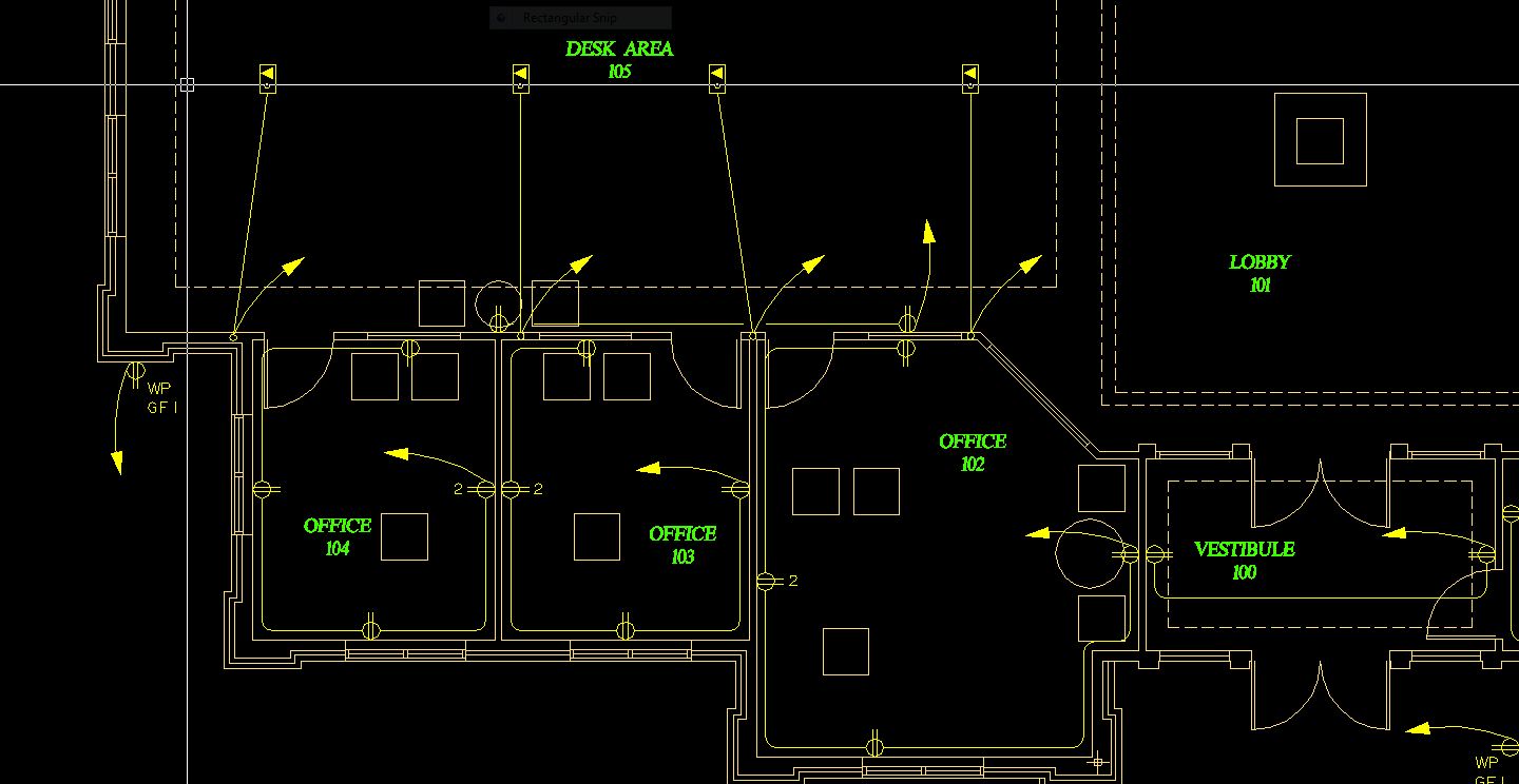
All in all, your traditional layout can be replicated in Revit with a little elbow grease. The image below is a quick example of an electrical layout. These receptacles belong to Electrical Circuits.

*Drawn in Revit MEP 2012
Corey D. 


──────────────────────────────────────────────────────────────────────
⁞|⁞ Please use .Accept as Solution and
  Give Kudos as appropriate to further enhance these forums. Thank you!
──────────────────────────────────────────────────────────────────────
⁞|⁞ Please use
.Accept as Solution and Give Kudos as appropriate to further enhance these forums. Thank you!
Message 3 of 5
04-30-2012
06:34 AM
- Mark as New
- Bookmark
- Subscribe
- Mute
- Subscribe to RSS Feed
- Permalink
- Report
04-30-2012
06:34 AM
How did you get the the wire from the floor box to appear like it is going up in the wall with the homerun coming out of it?
Message 4 of 5
04-30-2012
06:54 AM
- Mark as New
- Bookmark
- Subscribe
- Mute
- Subscribe to RSS Feed
- Permalink
- Report
04-30-2012
06:54 AM
The round circuit is a Junction Box: I loaded the OOTB family "Junction Boxes - No Load" and edited the family's annotation to remove the "J" and shrink the circle to 1/32" radius. When you create a circuit than contain an Electrical Device with the Part Type "Junction Box", the circuiting will want to route through that element. I clicked Arc Wire to generate the automatic layout, and then deleted the Homerun I didn't want. Then, I simply manually drew a wire from the Juntion Box to the Panel to make the new Homerun.


Corey D.
──────────────────────────────────────────────────────────────────────
⁞|⁞ Please use.Accept as Solution and Give Kudos as appropriate to further enhance these forums. Thank you!
──────────────────────────────────────────────────────────────────────
⁞|⁞ Please use
.Accept as Solution and Give Kudos as appropriate to further enhance these forums. Thank you!
Message 5 of 5
04-30-2012
07:04 AM
- Mark as New
- Bookmark
- Subscribe
- Mute
- Subscribe to RSS Feed
- Permalink
- Report
Reply
Topic Options
- Subscribe to RSS Feed
- Mark Topic as New
- Mark Topic as Read
- Float this Topic for Current User
- Bookmark
- Subscribe
- Printer Friendly Page
Forums Links
Can't find what you're looking for? Ask the community or share your knowledge.
Post to forums

