- Forums Home
- >
- Revit Products Community
- >
- Revit MEP Forum
- >
- Background updated now duct elbows are grayed out
Background updated now duct elbows are grayed out
- Subscribe to RSS Feed
- Mark Topic as New
- Mark Topic as Read
- Float this Topic for Current User
- Bookmark
- Subscribe
- Printer Friendly Page
- Mark as New
- Bookmark
- Subscribe
- Mute
- Subscribe to RSS Feed
- Permalink
- Report
I recently updated the architectural background I received from the architect. When I created ducts everything works fine. The issue comes when I do a turn. The elbows show but they are grayed out and I can not select them. I tried changing the view range but that didn't work. Every time I make an angle I get the same result, I can select them if I do a section but not when I'm working on the regular floor plan view. I only updated the background. Is there a setting that I need to updated or something else I can try?
Solved! Go to Solution.
Solved by jkarben. Go to Solution.
- Mark as New
- Bookmark
- Subscribe
- Mute
- Subscribe to RSS Feed
- Permalink
- Report
Just updating the background shouldn't cause this unless someone did a coordination review after it was updated.
I've seen something like this a long time ago. It turned out to be related to plan regions.
Sharing a small model representing the issue would help diagnose it.
Rob
Drafting is a breeze and Revit doesn't always work the way you think it should.
- Mark as New
- Bookmark
- Subscribe
- Mute
- Subscribe to RSS Feed
- Permalink
- Report
I attached the file. Please let me know if you need any other information, thanks, Rob.
- Mark as New
- Bookmark
- Subscribe
- Mute
- Subscribe to RSS Feed
- Permalink
- Report
Thanks for the model. I won't be able to look at it immediately but I will let you know what I find.
Rob
Drafting is a breeze and Revit doesn't always work the way you think it should.
- Mark as New
- Bookmark
- Subscribe
- Mute
- Subscribe to RSS Feed
- Permalink
- Report
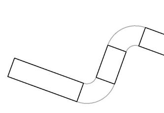
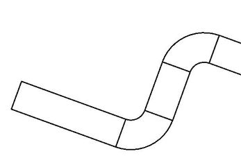
that's weird... i opened First Floor Mechanical Plan and see the halftone duct fittings when a making new duct segment. if you make a new view based on the same level the duct seemed to place fine. so i started poking around and noticed it has something to do with the View range. the current default elevation of duct when you place it (7'-4") is above the Cut Plane (6'). if you adjust the cut plane to 8' the fittings show as black.
cut plane at 6' cut plane at 8'

honestly not sure why yet :-), just something i noticed when poking around in your model.
@RobDraw any ideas?
Howard Munsell
Did you find this post helpful? Feel free to Like this post.
Did your question get successfully answered? Then click on the ACCEPT SOLUTION button.
- Mark as New
- Bookmark
- Subscribe
- Mute
- Subscribe to RSS Feed
- Permalink
- Report
I created a new view. The cut plane was at 4' or 4.5' and the ducts that were in the drawing appeared normal. Applying the plumbing view template properties and turning on the mechanical workset reveals the fittings showing normally. I poked around and could not find anything that might be causing this but it is something in the view settings, just not sure what and I've got work to do.
Also, I would consider getting away from suing worksets for visibility.
Rob
Drafting is a breeze and Revit doesn't always work the way you think it should.
- Mark as New
- Bookmark
- Subscribe
- Mute
- Subscribe to RSS Feed
- Permalink
- Report
@RobDraw correct, all the existing duct looked fine in the First Floor Mechanical Plan view i looked at as well. i had to draw a new piece of duct, with a couple bends, to see the issue.
Howard Munsell
Did you find this post helpful? Feel free to Like this post.
Did your question get successfully answered? Then click on the ACCEPT SOLUTION button.
- Mark as New
- Bookmark
- Subscribe
- Mute
- Subscribe to RSS Feed
- Permalink
- Report
It's the underlay setting. Set the underlay to None and the fittings will display properly.
As it is you're laying the same view as on underlay on top of First Floor Mechanical Plan. The levels associated to the Base and Top of the underlay creates a view with view range that is practically the same as the First Floor Mechanical Plan's view range, and they are competing.
The objective of the undelay is to display elements from another level, like the floor above.
- Mark as New
- Bookmark
- Subscribe
- Mute
- Subscribe to RSS Feed
- Permalink
- Report
Which setting is that? I unselected it in the image below but the issue still persists.
- Mark as New
- Bookmark
- Subscribe
- Mute
- Subscribe to RSS Feed
- Permalink
- Report
I figured out the setting you were referring to. Changing that setting fixed that issue but now I have another background issue. The architects have multiple levels and it works fine for them but when I import it I have to mess with the view range to make background areas appear or disappear. The weird thing is that is not a whole level just random walls and fixtures. I'll probably have to make plan regions to hide these items that shouldn't be showing up or try to change the view range and see if that works. Thanks for everybody's help.
- Mark as New
- Bookmark
- Subscribe
- Mute
- Subscribe to RSS Feed
- Permalink
- Report
Really.... the underlay.... i knew it was a view setting, just couldn't figure out which one. LOL Good Catch @jkarben .
Howard Munsell
Did you find this post helpful? Feel free to Like this post.
Did your question get successfully answered? Then click on the ACCEPT SOLUTION button.
- Mark as New
- Bookmark
- Subscribe
- Mute
- Subscribe to RSS Feed
- Permalink
- Report
Architect's view range is often very different then what we as MEP need it to be.
Try these settings to get the arch model to look like their view:
- Mark as New
- Bookmark
- Subscribe
- Mute
- Subscribe to RSS Feed
- Permalink
- Report
- Subscribe to RSS Feed
- Mark Topic as New
- Mark Topic as Read
- Float this Topic for Current User
- Bookmark
- Subscribe
- Printer Friendly Page


