Thank you Frank.
Thank you very much for providing so many good findings and suggestions about sketch grid. Now I have basically reported 3 different problems to our develop team as follows:
1. Sketch grid is not clear in some special direction like YZ, XY face under environment of "Infinity Pool".
2. Sketch grid will become clear when switching to other environment then switch back to "Infinity Pool", but it becomes unclear again if quit sketch and then re-enter sketch.
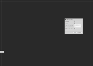
3. The starting reference number for "fixed grid setting" should be shown more logically. Now it is displayed as "Grid spacing" mulitplies "subdivisions", which is not good.
-> Right, this covers the three major issues I have with the grid. 🙂 If this would be fixed I think it would improve my workflow drastically.
You also mentioned some other problems which is current limitations, might needs some improvement as follows:
1. Snap to grid is not working when dragging sketch objects out of the sketch.
Currently the design is as above, so user should only be able to snap to grid while dragging sketch objects.
-> Maybe I missed your point, but aren't your both sentences contradictory?
I mean: It is per-design, that dragged sketch objects should snap to the grid but they don't snap when the user tries to drag them out of the old sketch's boundaries - e.d. extending the sketch spatially.
2.If set grid spacing with very small value, the sketch view performance is bad and grid is not clear to see.
Currently if user sets very small value to grid spacing, there would be too much grid shown for sketch. To display all the small grids, many graphic resources would be consumed, so some performance degrade can be expected. We currently do not limit user to input very small value for grid spacing. Do you have any suggestions to improve it?
-> As I have no insight to you rendering engine nor the grid implementation I cannot give you any specific suggestions obviously.
Looking at the current behavior of the grid subdivision I suppose that you work with absolute values and create the grid somewhat rigid into the worldspace. So I suppose you do all the fogging to limit the grid-object size in a "visually pleasant" way. 🙂
You have no dynamic correlation between the camera's frustrum, the object-distance and the grid - you generate it once for the given situation (sketch mode on the given plane) and that's it, am I right?


(No subdivisioning when getting "closer")
Therefore it becomes a performance issue if the user enters a high subdivision factor, because the grid object (worst case: the entire group individual grid lines) has to be available the hole time even if not inside the user's view - see last picture above (10cm^2 of grid area with 1cm per major line and a subdiv. factor of 100 makes 2000 line objects, +2 for the 0-lines - in case you draw one line per unit from edge to edge).
Generally speaking a performant and dynamic grid implementation should be generated depending on the distance of the camera to the targeted surface aka. sketch plane and it should not (excessively) extend the frustum of the FOV pyramid of the camera. The subdivision is then a limit of the max. visible amount of gird lines inside the camera's frustum. So the subdivisioning should work for both, zoom and dolly. If the user wants to have a more detailed snap control aka. see more grid lines he gets closer to the point of interest. This way previously visible grid lines leave the FOV, get eventually disposed if they are too far away and the count of currently visible grid lines decreases. So new lines can be generated without a big impact on the object count inside the scene graph. If the user moves away from the target, the max gridlines count overflows and the grid lines at the deepest level (aka. the most detailed level) get disposed while grid lines higher in the hierarchy get recreated. With a buffer for a few levels above and below the current detail level the user wouldn't even notice that (re)creation. It would result in a dynamic grid that gives the user a preceize controll on each detail level without having to adjust the grid continously and manually.
The grid settings should not contain an absolute major grid spacing value and a directly depending minor subdivision factor. It should have a factor per "unit" and a subdivison factor to generate lines between "units". So if I design my object in the metric system, the major lines should be e.g. every 10cm, 1cm, 1mm, 0.1mm etc. if the factor is chosen as 1/unit. With 0.5/unit it would be 5cm, 5mm, 0.5mm, 0.05mm etc. and the same goes for factors > 1 but the other direction. The subdivision factor would create the minor lines.


