Community
- Forums Home
- >
- Revit Products Community
- >
- Revit MEP Forum
- >
- revit mep family type parameter not resizing uniformly
Revit MEP Forum
Welcome to Autodesk’s Revit MEP Forums. Share your knowledge, ask questions, and explore popular Revit MEP topics.
Turn on suggestions
Auto-suggest helps you quickly narrow down your search results by suggesting possible matches as you type.
Reply
Topic Options
- Subscribe to RSS Feed
- Mark Topic as New
- Mark Topic as Read
- Float this Topic for Current User
- Bookmark
- Subscribe
- Printer Friendly Page
Message 1 of 9
Anonymous
1165 Views, 8 Replies
08-31-2012
04:16 AM
- Mark as New
- Bookmark
- Subscribe
- Mute
- Subscribe to RSS Feed
- Permalink
- Report
08-31-2012
04:16 AM
revit mep family type parameter not resizing uniformly
Hi,
I'm new to Revit MEP and a a parametric extrusion by setting the parameters for depth, width and height and have separations on the front face of tm using MEP 2011 to construct families for an electrical distribution panel. I madehe box drawn with model lines. Whenever I resize the height parameter, only the top part of the box resizes, keeping the rest of the separations the same size.
Is there a way to make Revit resize these separations uniformly? I tried using the equal dimension, but then it would just resize somwhere else and keep the ones I had the equality on the same. I also tried locking various dimensions, but it would just resize somewhere else.
Any help would be appreciated.
8 REPLIES 8
Message 2 of 9
Anonymous
in reply to:
Anonymous
08-31-2012
05:57 AM
- Mark as New
- Bookmark
- Subscribe
- Mute
- Subscribe to RSS Feed
- Permalink
- Report
08-31-2012
05:57 AM
For the benfit of us reading your posts, could you either post some screenshots or the fmaily for us to look at as it could be many things.
Initial ideas though are:-
- Are you using reference lines and/or planes to control the geometry?
- Are you dimensioning bewteen these reference elements and then locking the other geometric elements to these reference lines/planes?
- Have made a NAMED reference plane for the top geometry and assigned the lines to this reference plane then assigned dimensions to between this plane and another?
- Have you pinned the main axis reference planes and set the dimensions so that all movement in the family stems from the pinned reference planes. Otherwise objects move when they shouldn't?
- Using equals, have you made sure that the start/end of the equals dimensions are assigned to the edges of the family and not just the lines in the middle?
Hope the above questions make sense, but if not, best post the family for review.
Message 3 of 9
Anonymous
in reply to:
Anonymous
08-31-2012
06:24 AM
- Mark as New
- Bookmark
- Subscribe
- Mute
- Subscribe to RSS Feed
- Permalink
- Report
08-31-2012
06:24 AM
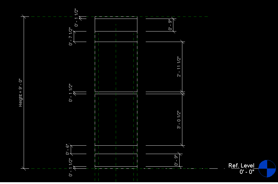
Here are a couple of screen shots for before resizing and after resizing. This is the front view of the box and I added dimensions to the model lines to see where it's resizing. I took off all of the equals and locks for the model lines so they are unconstrained apart from being on the front face.
Message 4 of 9
Anonymous
in reply to:
Anonymous
08-31-2012
06:35 AM
- Mark as New
- Bookmark
- Subscribe
- Mute
- Subscribe to RSS Feed
- Permalink
- Report
08-31-2012
06:35 AM
Do you have an image of what you are trying to achieve as I think you are not going to achieve it using the methods you are thinking of.
The 'eq' dimension is really used to allow an equi-distant spacin of elements within a set distance. it won't work in the same way on several unrelated single dimensions. Try adding labels to the dimensions which can then be formulas created in the "family types" area of the family editor. if the small dimensions are constant between the various sizes of the equipment, then you can set the distance and lock that dimension by clicking on the padlock that appears when you select a dimension.
Message 5 of 9
Anonymous
in reply to:
Anonymous
08-31-2012
06:54 AM
- Mark as New
- Bookmark
- Subscribe
- Mute
- Subscribe to RSS Feed
- Permalink
- Report
08-31-2012
06:54 AM
hi,
So attached is how I would like Revit to resize. Note that I moved the model lines around to acheive the result I wanted.
If I lock all the small dimensions and try to resize it, Revit just tries to break the constraints instead of resizing the unlocked dimensions.
Thanks for all your help!
Message 6 of 9
Anonymous
in reply to:
Anonymous
08-31-2012
07:05 AM
- Mark as New
- Bookmark
- Subscribe
- Mute
- Subscribe to RSS Feed
- Permalink
- Report
08-31-2012
07:05 AM
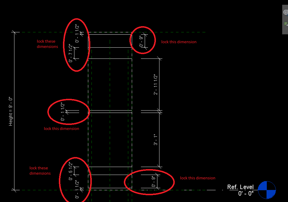
I think the attached should help but you will need to create some fomr of formula to define how the other two dimensions behave when the overll height changes.
One other question - why are you using model lines? Do you need to see these lines in any view other than a section or elevation of the front? If not then use symbolic lines
Message 7 of 9
Anonymous
in reply to:
Anonymous
08-31-2012
07:11 AM
- Mark as New
- Bookmark
- Subscribe
- Mute
- Subscribe to RSS Feed
- Permalink
- Report
08-31-2012
07:11 AM
I guess I could just define it via formulae, but I was also wondering why Revit just resizes that one block when there's no constraints applied to the rest.
I'm using model lines to define partitions in the panel instead of using separate extrusions as I assumed that it will keep the file smaller (Is this true?). I'd like to see it in all views as well.
Message 8 of 9
Anonymous
in reply to:
Anonymous
09-04-2012
07:08 AM
- Mark as New
- Bookmark
- Subscribe
- Mute
- Subscribe to RSS Feed
- Permalink
- Report
09-04-2012
07:08 AM
An update:
After locking everything else, Revit still only resizes the top part of the panel instead of splitting the height increase on the unlocked dimensions.
Any other thoughts on this?
Message 9 of 9
Anonymous
in reply to:
Anonymous
09-12-2012
12:31 PM
- Mark as New
- Bookmark
- Subscribe
- Mute
- Subscribe to RSS Feed
- Permalink
- Report
09-12-2012
12:31 PM
Sounds like you need some 'if" parameters.
Height = if(Max #1 Pole Breakers > 12, if(Max #1 Pole Breakers > 24, if(Max #1 Pole Breakers < 41, 42 Circuit Height, 30 Circuit Height), 24 Circuit Height), 12 Circuit Height)
You will need to create the circuit Height parameters for each one.
Specify the height for each panel.
Replace Height with Depth & Width.
Reply
Topic Options
- Subscribe to RSS Feed
- Mark Topic as New
- Mark Topic as Read
- Float this Topic for Current User
- Bookmark
- Subscribe
- Printer Friendly Page
Forums Links
Can't find what you're looking for? Ask the community or share your knowledge.
Post to forums

