Community
Revit Architecture Forum
Welcome to Autodesk’s Revit Architecture Forums. Share your knowledge, ask questions, and explore popular Revit Architecture topics.
Turn on suggestions
Auto-suggest helps you quickly narrow down your search results by suggesting possible matches as you type.
Reply
Topic Options
- Subscribe to RSS Feed
- Mark Topic as New
- Mark Topic as Read
- Float this Topic for Current User
- Bookmark
- Subscribe
- Printer Friendly Page
Message 1 of 19
03-09-2011
11:12 AM
- Mark as New
- Bookmark
- Subscribe
- Mute
- Subscribe to RSS Feed
- Permalink
- Report
03-09-2011
11:12 AM
So... I am working on a site plan and puttin in curbs... I want them to follow the contous of the site - I know there is a way but i can't think of it... How do i do this.
Thanks -
LD
If this helped solve your issue - remember to 'accept as solution' to help other find answers!
You can't think AutoCAD and run Revit.
Email: LisaDragoEE@gmail.com
Solved! Go to Solution.
18 REPLIES 18
Message 2 of 19
03-09-2011
02:45 PM
- Mark as New
- Bookmark
- Subscribe
- Mute
- Subscribe to RSS Feed
- Permalink
- Report
03-09-2011
02:45 PM
The only way I know is this: create profiles, load them into project. Create model lines that follow the edge that you want to convert into a curb (because you can't use "pick lines" on the site), then use "pick path" > "pick 3d edges" and select the model lines that you created, finish the path, select profile, pick a profile from the list.
Alfredo Medina _________________________________________________________________ ______
Licensed Architect (Florida) | Freelance Instructor | Profile on Linkedin
Message 3 of 19
03-09-2011
03:26 PM
- Mark as New
- Bookmark
- Subscribe
- Mute
- Subscribe to RSS Feed
- Permalink
- Report
Message 4 of 19
03-09-2011
03:36 PM
- Mark as New
- Bookmark
- Subscribe
- Mute
- Subscribe to RSS Feed
- Permalink
- Report
03-09-2011
03:36 PM
Oops, it seems that you posted in the wrong thread? Surface patterns?
Alfredo Medina _________________________________________________________________ ______
Licensed Architect (Florida) | Freelance Instructor | Profile on Linkedin
Message 5 of 19
03-09-2011
03:40 PM
- Mark as New
- Bookmark
- Subscribe
- Mute
- Subscribe to RSS Feed
- Permalink
- Report
Message 6 of 19
03-10-2011
05:02 AM
- Mark as New
- Bookmark
- Subscribe
- Mute
- Subscribe to RSS Feed
- Permalink
- Report
03-10-2011
05:02 AM
Okay Maybe i am missing something or it is just too early to think Alfredo - but i am having trouble getting in the model line to follow the contours... Any thoughts?
LD
If this helped solve your issue - remember to 'accept as solution' to help other find answers!
You can't think AutoCAD and run Revit.
Email: LisaDragoEE@gmail.com
Message 7 of 19
03-10-2011
09:50 AM
- Mark as New
- Bookmark
- Subscribe
- Mute
- Subscribe to RSS Feed
- Permalink
- Report
03-10-2011
09:50 AM
As I said in my previous reply, "pick lines" does not work with contours, you have to create model lines on top of them, without the help of pick lines, unfortunately.
Alfredo Medina _________________________________________________________________ ______
Licensed Architect (Florida) | Freelance Instructor | Profile on Linkedin
Message 8 of 19
03-10-2011
11:52 AM
- Mark as New
- Bookmark
- Subscribe
- Mute
- Subscribe to RSS Feed
- Permalink
- Report
03-10-2011
11:52 AM
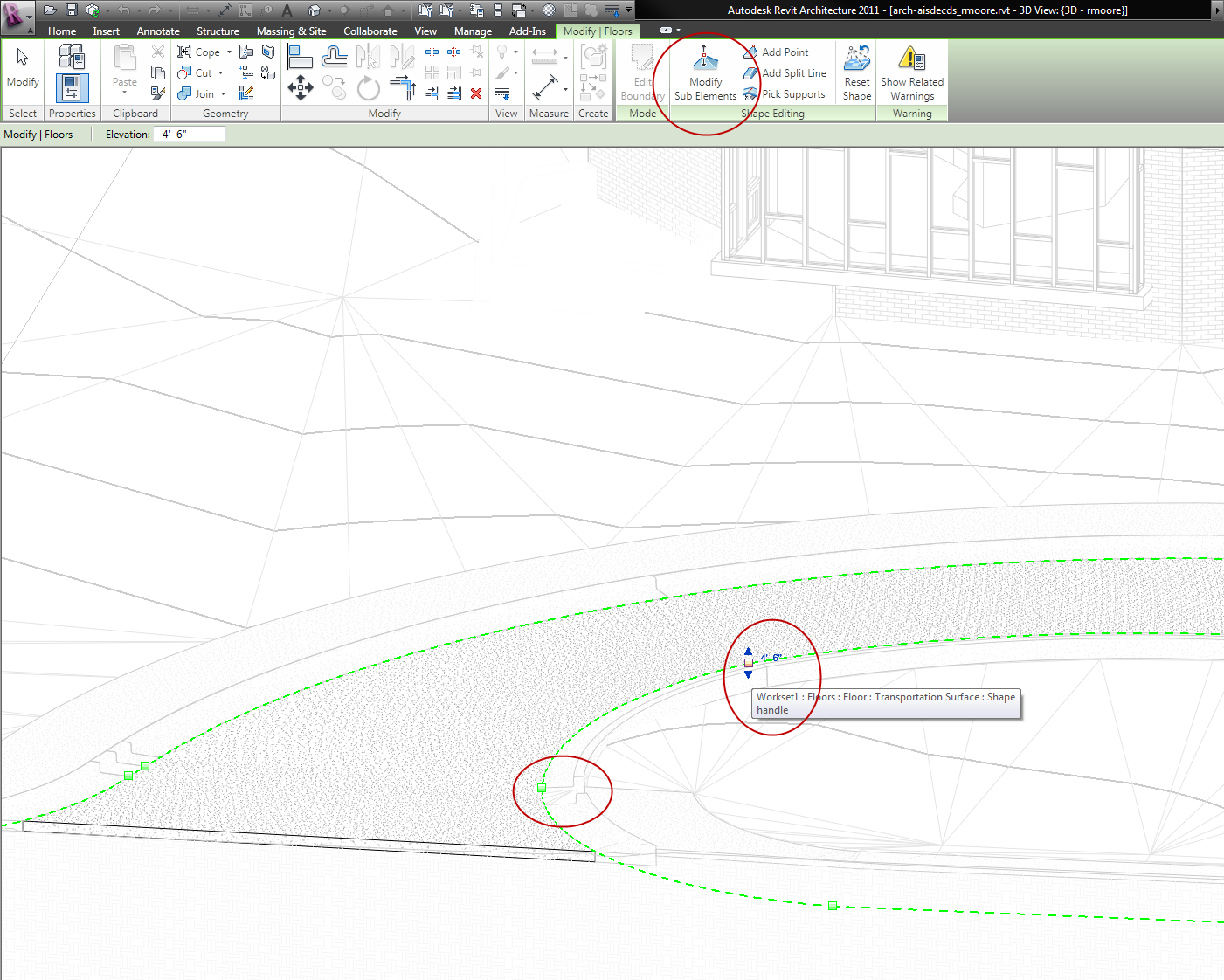
I made the roadway in plan first, then edited the sub elements to roughly follow the countours, then added a sweep blend with the curb profile. Unfortunately it's a PITA and sometimes wouldn't let me create the sweep, leaving gaps in the curb.
This is my first job where I tried to model the site, if anyone has a more humane way of doing this i'm all ears.
Message 9 of 19
04-25-2013
11:46 AM
- Mark as New
- Bookmark
- Subscribe
- Mute
- Subscribe to RSS Feed
- Permalink
- Report
04-25-2013
11:46 AM
Unfortunately this is a PAINFULLY time consuming and (IMO an embarrassment for Autodesk) process. I can't believe that a software as powerful as Revit still lacks basic site tools beyond creating topo. I'm not asking for much but a tool to create a road or curb that follows the surface shouldn't be that hard. I find it hard to believe with the resources that Autodesk has that they can't devote something towards developing some tools.
My suggestion, if you can afford it, would be to look at eagle point.
Otherwise, you might try using an adaptive family. I looked at this recently and I thought it may be possible to create a family that would allow you to adjust the elevation as you enter each point
My suggestion, if you can afford it, would be to look at eagle point.
Otherwise, you might try using an adaptive family. I looked at this recently and I thought it may be possible to create a family that would allow you to adjust the elevation as you enter each point
Message 11 of 19
02-15-2014
04:37 AM
- Mark as New
- Bookmark
- Subscribe
- Mute
- Subscribe to RSS Feed
- Permalink
- Report
02-15-2014
04:37 AM
There is a limitation about using "pick lines" on the topography. To overcome this limitation, we could try this: export the topography, and import or link it back. Now we should be able to create a sweep using "pick 3d edges" on the contours imported from the topography (note: be aware that using pick lines on dwg files might create some issues or inaccuracies). If I remember correctly, that is the same technique that Marcello Sgambelluri has demonstrated in his classes on topography. If it is not, I am pretty sure he will come to this thread and help us.
All of us agree that Autodesk should come up with a specific tool to do this in a simple way. There are already some third party tools to make these curbs. I have seen them in conferences.
If it helps, here's a link to a video I did in April 2012, that could still be an alternative. The points in the video go around a curvy shape, which is flat, but since the points are adaptive, they could have different elevations as well. This is a family that is created with the generic model adaptive template, with a profile that was made with a flat generic model family :
Alfredo Medina _________________________________________________________________ ______
Licensed Architect (Florida) | Freelance Instructor | Profile on Linkedin
Message 12 of 19
02-15-2014
05:23 PM
- Mark as New
- Bookmark
- Subscribe
- Mute
- Subscribe to RSS Feed
- Permalink
- Report

Message 13 of 19
Anonymous
in reply to:
Anonymous
02-18-2014
09:50 AM
- Mark as New
- Bookmark
- Subscribe
- Mute
- Subscribe to RSS Feed
- Permalink
- Report
02-18-2014
09:50 AM
Alfredo, Marcello,
Thank you both for your responses.
Alfredo:
I saw your video a while back, very informative, thanks. I started working with the adaptive families but have gotten away from them. I think it's time to go back and revisit.
Marcello, fantastic job! Unfortunately I haven't been able to attend AU in several years so I was not able to attend your class. This should lower my frustration level significantly. Perhaps Autodesk will incorporate some of your processes into Revit.
A couple of questions/issues.
1. When I import the drawing back in to Revit the spline will not allow me to pick the points on the DWG to set the nodes. I do not have much familiarity with massing as we don't have a great deal of need for it other than very simple shapes. So I know it's something I'm missing. I appears to be drawing the spline in on whatever plane is being used as a reference. It will allow me to pick the edges of the drawing but nothing else. I also tried it with the sample file you provided to see if it was something I had set wrong in my project but had the same result.
The beam method should work for now until I get the spline issue figured out.
2. What is your feeling on parking lots. I've used various methods. Typically I create a flat area, using either a floor or building pad and adjust the site but sometimes this takes a fair amount of manipulation as the parking lot slopes from one side of the building to the other. The issue isn't really the parking lot itself but the stripping that becomes an issue. I've even gone as far as subdividing the topo and for the stripping but this is EXTREMELY tedious and only used when I have no other choice.
3. Any ideas on the lousy text editor?
Message 14 of 19
Anonymous
in reply to:
Anonymous
02-18-2014
11:29 AM
- Mark as New
- Bookmark
- Subscribe
- Mute
- Subscribe to RSS Feed
- Permalink
- Report
02-18-2014
11:29 AM
Update.
I created a mass and imported the DWG. I then created a second mass and was able toy use the first mass to pick the points for the spline. That may have been the process you used but I missed that. Works nicely after I figured that one out. The only problem I had was Revit kept telling me there was a serious error and wanting me to save a recovery file. That eventually went away. I'm not sure if it was a graphics issue.
One other question, when you used the splines to generate the fence along the side, did you copy those original splines for use later? It appears that when you create the form to use for the road it deletes the original splines. I'm assuming you made a copy but I wasn't sure if there was a setting that would keep the original defining edges.
Message 17 of 19
Anonymous
in reply to:
Anonymous
02-20-2014
10:43 AM
- Mark as New
- Bookmark
- Subscribe
- Mute
- Subscribe to RSS Feed
- Permalink
- Report
02-20-2014
10:43 AM
Marcello,
I can't tell you how much I appreciate the information you provided. It's already proved to be invaluable. Using your techniques i was able to come up with parking striping that follows the contour.
Thanks again.
Message 18 of 19
Anonymous
in reply to:
Anonymous
02-24-2014
12:17 PM
- Mark as New
- Bookmark
- Subscribe
- Mute
- Subscribe to RSS Feed
- Permalink
- Report
02-24-2014
12:17 PM
Marcello,
Thought this might interest you. Here's a macro for creating model lines from the topo edges.
http://boostyourbim.wordpress.com/category/site/
Reply
Topic Options
- Subscribe to RSS Feed
- Mark Topic as New
- Mark Topic as Read
- Float this Topic for Current User
- Bookmark
- Subscribe
- Printer Friendly Page
Forums Links
Can't find what you're looking for? Ask the community or share your knowledge.
Post to forums

