Community
- Forums Home
- >
- Revit Products Community
- >
- Revit Architecture Forum
- >
- Complex pipe structure & reference planes
Revit Architecture Forum
Welcome to Autodesk’s Revit Architecture Forums. Share your knowledge, ask questions, and explore popular Revit Architecture topics.
Turn on suggestions
Auto-suggest helps you quickly narrow down your search results by suggesting possible matches as you type.
Reply
Topic Options
- Subscribe to RSS Feed
- Mark Topic as New
- Mark Topic as Read
- Float this Topic for Current User
- Bookmark
- Subscribe
- Printer Friendly Page
Message 1 of 3
Anonymous
815 Views, 2 Replies
10-22-2013
08:29 PM
- Mark as New
- Bookmark
- Subscribe
- Mute
- Subscribe to RSS Feed
- Permalink
- Report
10-22-2013
08:29 PM
Hi All,
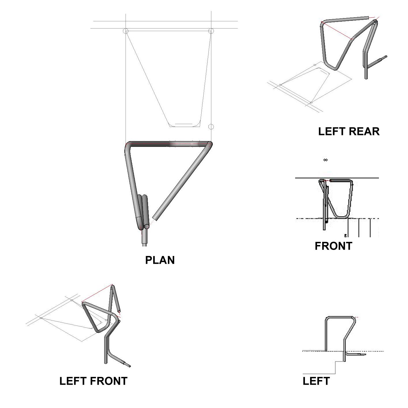
Attached is an image of one of the many Complex pipe structures that I am working on for steel fabrication (family), you need to look at it first to get an idea of what I am trying to acheive.
I am creating these pipes using sweeps with reference lines at their centres, then I trace over them in 3D using pick path command when creating the extrusion. Is this a good way of doing it?
In trying to draw this particular element I have hit a problem. Drawing the curves that join the straights has become difficult as the straights don't align easily, and so I was wondering if there is a way of creating a reference plane by picking 3 points in 3d? This would be really, really useful!
The curve at the top left of the 'plan' joining the straights is difficult to draw as the straight on the left comes back at an angle and not perpendicular to say the rear vertical pipe work, which is drawn using another plane. I have managed to draw this so far by aligning it by eye, a dodgy way which is not really acceptable.
Found a way I think. A major part of the problem is that you cannot draw a reference plane in 3d! So after I have oriented to a plane perpendicular to the direction I want to draw, I then can draw an extrusion and then rotate the view in 3d and pick the face of the extrusion that aligns with the plane I want to draw on. A bit finicky really. Is there a better way?
I have used the align to plane in 3d
Can anyone give me a clue how this all could be better done?
Thanks in advance,
Raoul
Solved! Go to Solution.
Solved by Alfredo_Medina. Go to Solution.
2 REPLIES 2
Message 2 of 3
10-23-2013
08:07 AM
- Mark as New
- Bookmark
- Subscribe
- Mute
- Subscribe to RSS Feed
- Permalink
- Report
10-23-2013
08:07 AM
Draw a dummy solid first, to be used as a guide to draw model lines and fillet curves on its faces. Then, use swep with "pick 3d edges". As in this example:

Alfredo Medina _________________________________________________________________ ______
Licensed Architect (Florida) | Freelance Instructor | Profile on Linkedin
Message 3 of 3
10-23-2013
04:19 PM
- Mark as New
- Bookmark
- Subscribe
- Mute
- Subscribe to RSS Feed
- Permalink
- Report
10-23-2013
04:19 PM
Thanks for that Alfredo. Part of my issue is that a lot of this job is not rectiliniar, but in essence this method looks really good.
Cheers,
Raoul
Reply
Topic Options
- Subscribe to RSS Feed
- Mark Topic as New
- Mark Topic as Read
- Float this Topic for Current User
- Bookmark
- Subscribe
- Printer Friendly Page
Forums Links
Can't find what you're looking for? Ask the community or share your knowledge.
Post to forums

