Community
- Forums Home
- >
- Revit Products Community
- >
- Revit MEP Forum
- >
- Re: Pipe Annalysis, Revit PIpe Sizing, flow GPM
Revit MEP Forum
Welcome to Autodesk’s Revit MEP Forums. Share your knowledge, ask questions, and explore popular Revit MEP topics.
Turn on suggestions
Auto-suggest helps you quickly narrow down your search results by suggesting possible matches as you type.
Reply
Topic Options
- Subscribe to RSS Feed
- Mark Topic as New
- Mark Topic as Read
- Float this Topic for Current User
- Bookmark
- Subscribe
- Printer Friendly Page
Message 1 of 25
03-14-2017
07:27 AM
- Mark as New
- Bookmark
- Subscribe
- Mute
- Subscribe to RSS Feed
- Permalink
- Report
03-14-2017
07:27 AM
Pipe Annalysis, Revit PIpe Sizing, flow GPM
My question is, my cold water connection to a lav is wanting to size it to 1" using the pipe sizing tool in Revit. This should be sizing at 1/2" like the hot water is. I have checked the family, I cannot think of where else to look.
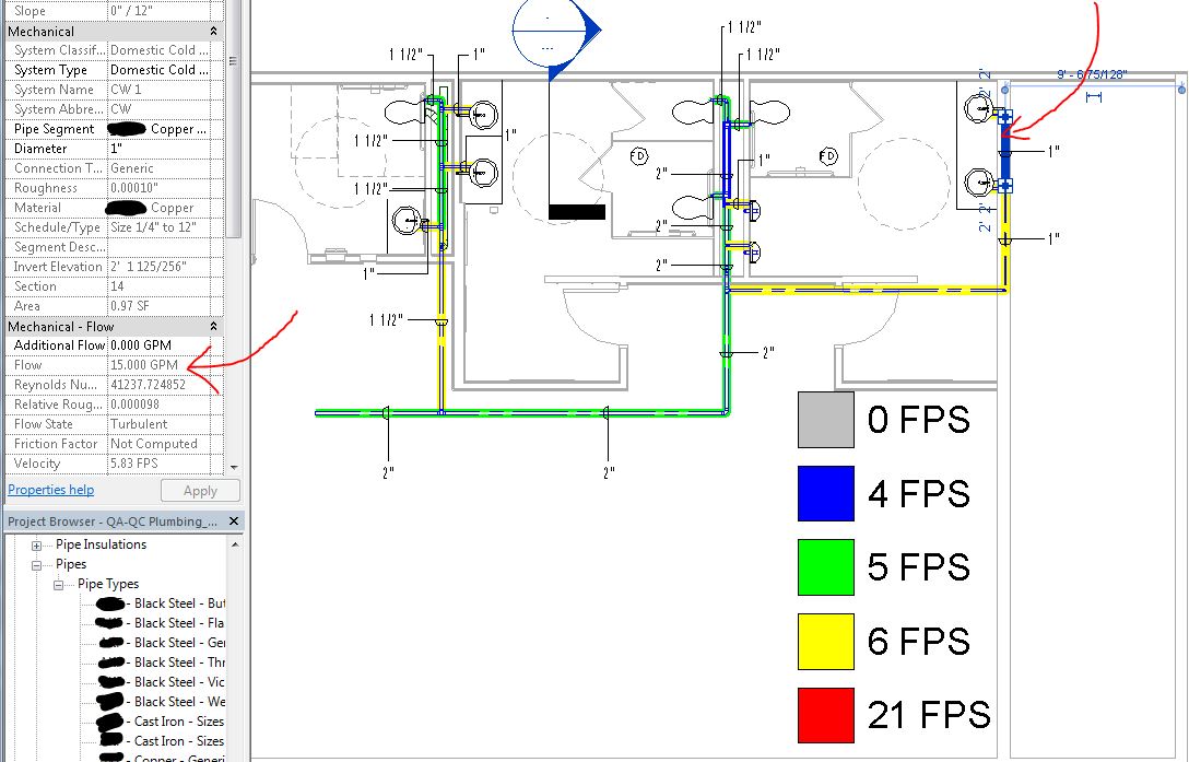
The only difference I notice is when I click on the HW pipe that is connected to my lav family it says in the properties box, under Mechanical that the GPM is 4, which is correct.
However when I click on the CW which is connected to the Lav also it reads 15 GPM which is wrong, and the Reynolds number comes up incorrect.
I cannot find anywhere to fix this, as its all greyed out in the properties box, I have tried to look under families in the pipe systems, I have looked in the lav family as well.
Its the Grey Pipe that is coming up at 21 FPS, this is due to me manually changing the size to 1/2" for Cold water.
In the second picture if I use the pipe size tool in Revit it bumps it up to 1", which is the 2nd picture. Which is wrong...
If I click on the hot water pipe that is sizing correctly from the lav family, here in the 3rd picture is the Mechanical flow gpm in the properties box. As you can see its all greyed out. and 4GPM is correct.
When I click on the CW pipe as you can see in the 3rd picture the Mechanical flow GPM is 15 which is incorrect, and the Reynolds number is also incorrect it should be matching the same number that the Hw is under.
Anyone have any ideas on how I can get the cold water to read 4GPM to size it correctly?
Inside the family its set at 1.5 HWFU, and 1.5 CWFU, there is no other areas to change in the family.
24 REPLIES 24
Message 2 of 25
03-14-2017
03:19 PM
- Mark as New
- Bookmark
- Subscribe
- Mute
- Subscribe to RSS Feed
- Permalink
- Report
03-14-2017
03:19 PM
Hello-
Understanding where all these numbers come from can be a bit like unscrambling the word jumble in the daily newspaper.
There is a setting on the System Type called "Flow Conversion Method". To find this, select a pipe, select the Piping Systems tab in the Ribbon, click the Edit Type button in the Properties Palette).
On your cold water system type, if you change your method from "Predominantly Flush Valves" to "Predominantly Flush Tanks", you should see the same results for cold water as what you are seeing for hot water.
However, once you have done this, and have the same flow conversion from fixture units, you will still have different Reynolds numbers, since, in addition to the flow velocity, this is dependent on the viscosity and density which are quite different at cold water temperatures vs. hot water temperatures.
Hope that helps,
MS
Martin Schmid
Product Line Manager
Mechanical Detailing and Electrical Design
Architecture, Engineering, and Construction
Autodesk, Inc.
Message 3 of 25
03-15-2017
06:04 AM
- Mark as New
- Bookmark
- Subscribe
- Mute
- Subscribe to RSS Feed
- Permalink
- Report
03-15-2017
06:04 AM
Hello, yes this make sense. However, although it fixed the Bathroom CW lavs to be correct, it also changed the rest of the system to be incorrect.
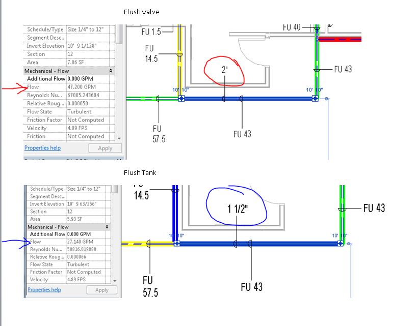
Where the piping under Flush Valves was reading 43FU, which is 47.2 GPM for a flush valve was sizing a 2"CW pipe. Once I changed the system to flush tank and used the pipe sizing tool in Revit, it changed the system to 42FU, which is 27.14 GPM, which changed the size down to 1-1/2", which is incorrect.
Is there a add in to help with this? Or what do you suggest to fix this?
Message 4 of 25
03-15-2017
06:16 AM
- Mark as New
- Bookmark
- Subscribe
- Mute
- Subscribe to RSS Feed
- Permalink
- Report
03-15-2017
06:16 AM
At this point, the whole system is either defined as 'Flush Valve' or 'Flush Tank'.
Are you indicating that part of the system needs to be sized as flush valve (e.g., the blue below) and part of it needs to be sized based on flush tank (as shown in orange). How would you determine the size for the green pipe (which is some combination)?

Martin Schmid
Product Line Manager
Mechanical Detailing and Electrical Design
Architecture, Engineering, and Construction
Autodesk, Inc.
Message 5 of 25
03-15-2017
06:26 AM
- Mark as New
- Bookmark
- Subscribe
- Mute
- Subscribe to RSS Feed
- Permalink
- Report
03-15-2017
06:26 AM
In the example you gave, yes this would be predominantly Flush Tank. However In my case the system would be Flush Valve.
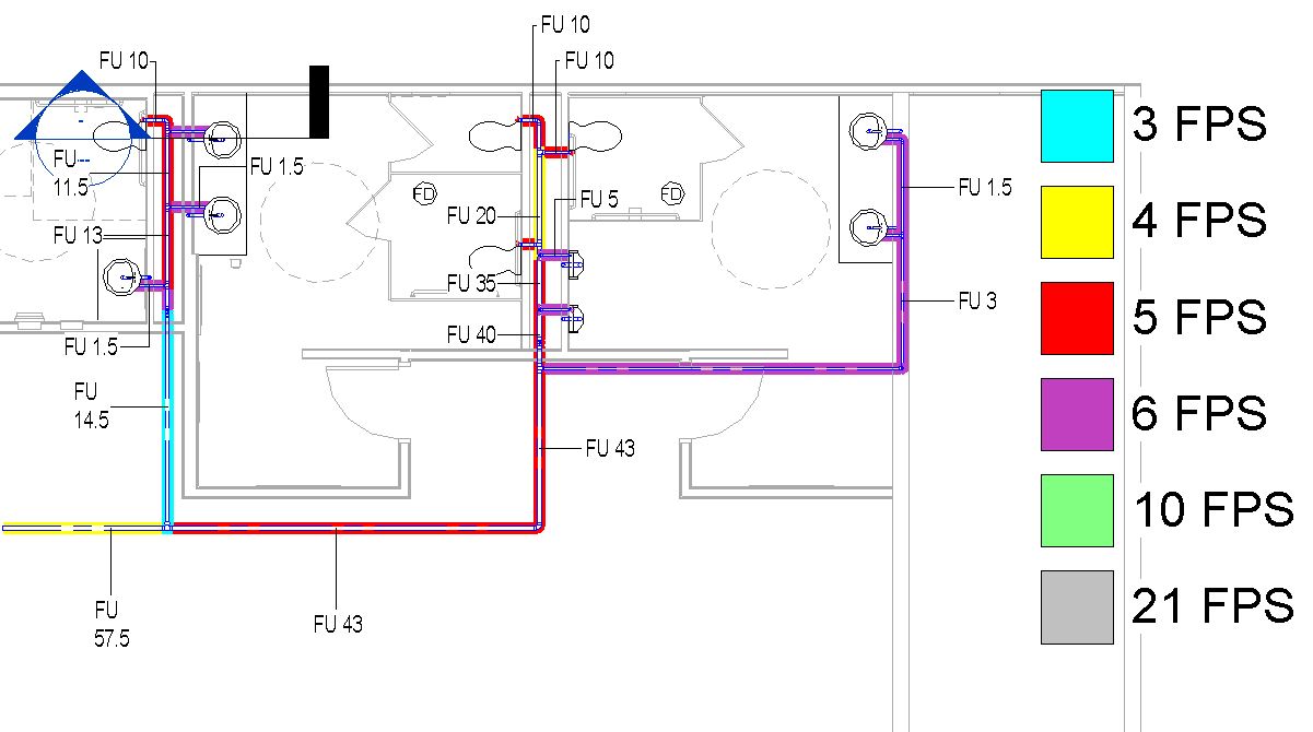
In the picture attached, you can see the flush valve system is all sized correctly accept for the CW going to the LAV's, its picking up 15GPM and Revit is auto sizing it with the pipe sizing tool to 1" and this is incorrect.
So If I manually change the pipe to the size it should be 1/2", and analyze the system it ends up showing 21 FPS which its appearing too high, although its actually correct.
Message 6 of 25
03-15-2017
07:15 AM
- Mark as New
- Bookmark
- Subscribe
- Mute
- Subscribe to RSS Feed
- Permalink
- Report
03-15-2017
07:15 AM
The default software code written to convert "Fixture Units (FU)" to "Flow (GPM)" via Hunter’s Curve does not account for fixture units below 5FU for "Predominantly Flush Valve Supply Systems." It currently assumes 15.0 GPM for anything ≤5FU for “Predominantly Flush Valve Supply Systems”
Is there anything to override this, or a add in to fix this?
Message 7 of 25
03-15-2017
07:20 AM
- Mark as New
- Bookmark
- Subscribe
- Mute
- Subscribe to RSS Feed
- Permalink
- Report
03-15-2017
07:20 AM
Can you clarify: "In the example you gave, yes this would be predominantly Flush Tank. However In my case the system would be Flush Valve."
What is predominantly Flush Tank: The green line? the blue line? the orange line? the whole system? how do you know? Is this based on the quantity of fixtures (3 flush tanks vs. 1 flush valve), or is it based on fixture units (e.g., lets say the FV in that sample is 15 FU, but the FTs are only 1.5 FUs each)..
I may have mis-understood, but I was interpreting that you wanted part of the system sized as Flush Tank and part as Flush Valve... is that not the case?
I want to understand your statement better:
"42FU, which is 27.14 GPM, which changed the size down to 1-1/2", which is incorrect. "
What is incorrect... the flow rate (27,14 GPM) or size (1-1/2")?
How are you determining the size? Revit uses velocity based on the inside diameter or friction based on the inside diameter... a lot of plumbing designers us a lookup table instead (e.g., for each range of FUs, use a defined pipe size). An add-in may be able to do this for you, or even dynamo.
Martin Schmid
Product Line Manager
Mechanical Detailing and Electrical Design
Architecture, Engineering, and Construction
Autodesk, Inc.
Message 8 of 25
03-15-2017
07:25 AM
- Mark as New
- Bookmark
- Subscribe
- Mute
- Subscribe to RSS Feed
- Permalink
- Report
03-15-2017
07:25 AM
Yes, please see this post: https://forums.autodesk.com/t5/revit-api-forum/usermep-calculation-addin/td-p/4968174
Martin Schmid
Product Line Manager
Mechanical Detailing and Electrical Design
Architecture, Engineering, and Construction
Autodesk, Inc.
Message 9 of 25
03-15-2017
07:52 AM
- Mark as New
- Bookmark
- Subscribe
- Mute
- Subscribe to RSS Feed
- Permalink
- Report
03-15-2017
07:52 AM
If it was all public, and assuming in your example the FV is 15 FU, and the Ft’s are 1.5FU, then it would be sized on the Flush Valve because it’s the greater fixture unit value. So the whole system would be sized as Flush Valve. However according to the sizing system in Revit it will not size at 1.5FU it will round up to 15GPM.
Everything in my example in the screen shots was being sized as a Flush Valve System.
My statement, "42FU, which is 27.14 GPM, which changed the size down to 1-1/2", which is incorrect. "
What is incorrect... the flow rate (27,14 GPM) or size (1-1/2")?
Those values where based upon the Flush Tank system and the Auto sizing the revit tool has. I tried to switch to that system to fix the Bathroom Lavs sizing and GPM, which the Flush tank system took care of. It then changed the main sizes based on a Flush Tank system, and I needed it to remain sized based on the Flush Valve System, since that pipe needs to be 2” .
I am attempting to use the Pipe Sizing tool in Revit to calculate this, instead of sizing it manually like I normally would. I am helping to develop a QA/QC process with this and also using the Pipe Legend to visually analyze the system.
In this picture my system would be predominantly flush Valve, so the LAV’s are not sizing correctly using the pipe sizing tool in Revit due to the default software code written to convert FU to GPM, since its assuming 15.0GPM for anything under 5FU under the flush valve system.
Message 10 of 25
03-15-2017
07:56 AM
- Mark as New
- Bookmark
- Subscribe
- Mute
- Subscribe to RSS Feed
- Permalink
- Report
Message 11 of 25
03-15-2017
08:26 AM
- Mark as New
- Bookmark
- Subscribe
- Mute
- Subscribe to RSS Feed
- Permalink
- Report
Message 12 of 25
03-15-2017
10:43 AM
- Mark as New
- Bookmark
- Subscribe
- Mute
- Subscribe to RSS Feed
- Permalink
- Report
03-15-2017
10:43 AM
>> However according to the sizing system in Revit it will not size at 1.5FU it will round up to 15GPM.
OK, I see that too.
What flow rate values would you expect below 5 FU? Are those in this image what you would expect... are the values below as you would expect? Would you ever have less than 1 FU?
1 FU > 3 GPM
2 FU > 5
3 FU > 6.5
4 FU > 8
>> Those values where based upon the Flush Tank system and the Auto sizing the revit tool has.
which values are you saying are incorrect? The GPM or the size?
If you are referring to the size, which method are you using in the sizing tool? Friction or Velocity, and what value for Friction or Velocity are you using.. and what type of pipe are you using? e.g., a pipe sized at 4 GPM may be smaller than a pipe sized at 3.5 GPM. sizing takes into account the inside diameter of the pipe.. e.g., Copper K, L, M each have different ID, so depending on what method you employ, it is possible that a slightly different velocity or a slightly different pipe size is enough to nudge the size between 1.5" vs. 2".
>> In this picture my system would be predominantly flush Valve
So, everything in the system would be sized using the "system wide" setting for Flush Valve, but that is problematic because the table only goes down to 5 FU, is that right?
Martin Schmid
Product Line Manager
Mechanical Detailing and Electrical Design
Architecture, Engineering, and Construction
Autodesk, Inc.
Message 13 of 25
03-15-2017
11:23 AM
- Mark as New
- Bookmark
- Subscribe
- Mute
- Subscribe to RSS Feed
- Permalink
- Report
03-15-2017
11:23 AM
"At this point, the whole system is either defined as 'Flush Valve' or 'Flush Tank'."
Why not make the green line (and orange, and blue for that matter) user definable? I think you and I could both come up with a situation where the green line should be flush valve or flush tank. Divide the system at the Tee and each system has flush tank or flush valve sizing options. Then I can use an addin to get the Flow Conversion Method parameter, and the Fixture Units of each pipe and size it based on my own defined lookup table that you referenced.
Defaulting to 15 GPM on systems that can only be defined entirely as flush valve kind of makes the auto-size feature useless, as most of the pipes to the small fixtures will be way oversized.
Message 14 of 25
03-15-2017
04:40 PM
- Mark as New
- Bookmark
- Subscribe
- Mute
- Subscribe to RSS Feed
- Permalink
- Report
03-15-2017
04:40 PM
Hi mwilson:
"Why not make the green line (and orange, and blue for that matter) user definable? I think you and I could both come up with a situation where the green line should be flush valve or flush tank."
The spirit of my question was understanding if the system as a whole is flush tank or flush valve, or if section of piping in a system need to be evaluated as to if they are predominantly one or the other. Sounds like you're advocating for the each section needs to be evaluated option?
>> Then I can use an addin to get the Flow Conversion Method parameter, and the Fixture Units of each pipe and size it based on my own defined lookup table that you referenced.
Realistically, there is nothing stopping an add-in developer from doing this now. One doesn't need to use our built-in FU to GPM table to do this, particularly if the logic is Fixture Units to SIze lookup.
>> Defaulting to 15 GPM on systems that can only be defined entirely as flush valve kind of makes the auto-size feature useless, as most of the pipes to the small fixtures will be way oversized.
Understood.. what fixture unit/flow rates would you expect below the 15 gpm threshold?
Would a fixture units to Size Lookup be preferred? Why?
Martin Schmid
Product Line Manager
Mechanical Detailing and Electrical Design
Architecture, Engineering, and Construction
Autodesk, Inc.
Message 15 of 25
03-16-2017
08:30 AM
- Mark as New
- Bookmark
- Subscribe
- Mute
- Subscribe to RSS Feed
- Permalink
- Report
03-16-2017
08:30 AM
"The spirit of my question was understanding if the system as a whole is flush tank or flush valve, or if section of piping in a system need to be evaluated as to if they are predominantly one or the other. Sounds like you're advocating for the each section needs to be evaluated option?"
Sorry if I misunderstood your question. Yes, I absolutely think that each section needs to be evaluated as the user defines it. Using fixture units to size piping is a guideline, not a rule. As you know, when sizing piping for a sports arena for example, fixture units go right out the window, since they're not appropriate. Being able to define sections of the system with different sizing methods, such as fixture units to gpm to pipe size or gpm to pipe size, would really help the automatic sizing be more robust.
"Understood.. what fixture unit/flow rates would you expect below the 15 gpm threshold?"
I just found the Revit addin which allows me to define flow rates below 5 FU/15 GPM, which I believe is the holy grail. Since the IPC doesn't define these values, rather than me saying what I think it should be, and hard coding that into the software, giving the user the option to define those values is absolutely perfect. Honestly it just makes me beam with excitement that the auto sizing feature may actually be useful on a future project.
"Would a fixture units to Size Lookup be preferred? Why?"
I don't mean to sound like a broken record, but a user definable option would be best IMHO. I just mentioned that option because you mentioned it, and was trying to point out that with sizing plumbing piping there is more than one way to skin a cat. It's not an exact science.
Much obliged.
Message 16 of 25
03-23-2017
08:33 PM
- Mark as New
- Bookmark
- Subscribe
- Mute
- Subscribe to RSS Feed
- Permalink
- Report
03-23-2017
08:33 PM
Butting in late in the thread sorry.
>> Would a fixture units to Size Lookup be preferred? Why?
Yes.
Because IPC is valid in 35 US states and Guam, according to their own data. The whole rest of the world would also like to use fixture unit to flow conversion.
Source; http://www.iccsafe.org/international-code-adoptions/
Message 17 of 25
03-26-2017
12:30 PM
- Mark as New
- Bookmark
- Subscribe
- Mute
- Subscribe to RSS Feed
- Permalink
- Report
03-26-2017
12:30 PM
Having tried the pipe sizing tool I can confirm that the resultant sizing is miles off what it should be.
The mechanical engineer I was trying to help out laughed at me and threw the lot in the bin and started again with manual sizing.
It's useless.
Message 18 of 25
03-26-2017
05:29 PM
- Mark as New
- Bookmark
- Subscribe
- Mute
- Subscribe to RSS Feed
- Permalink
- Report
03-26-2017
05:29 PM
Hi Kevin- Thanks for the post.
Indeed, there are a number of limitations in the pipe sizing tool... before getting to that, I'll digress a bit...
"A lumberjack comes across a man in the forest. The man is working hard trying to chop down a tree by hitting it with a hammer. The lumberjack stops the man and says, “Hey, you’re using the wrong tool! Try this…” and hands the man a saw. The man thanks him, and the lumberjack continues on his way, happily knowing that he’s helped. The man then begins striking the tree with the saw the same way he was with the hammer."
In some cases, what we've given you is a handsaw, but what you want is a chain saw. In other cases, depending on regional code rules and such, what we've given you is a saw, but it ends up being applied like a hammer.
Can you elaborate a bit on the scenario in which you attempted to apply the sizing tool(s)? What kind of system? what sizing rules were you expecting that weren't happening?
As reported in the Revit Roadmap, we are making improvements to the analytical capabilities, there are specific areas that this will address in the nearer term, and things we know we won't be getting to right away. However, I'd like to understand a bit more about your scenario as another data point to feed into our improvement planning
Thanks,
Martin Schmid
Product Line Manager
Mechanical Detailing and Electrical Design
Architecture, Engineering, and Construction
Autodesk, Inc.
Message 19 of 25
03-27-2017
06:09 AM
- Mark as New
- Bookmark
- Subscribe
- Mute
- Subscribe to RSS Feed
- Permalink
- Report
03-27-2017
06:09 AM
Can everyone please go vote here so Autodesk will create the fix?
Message 20 of 25
03-29-2017
03:46 PM
- Mark as New
- Bookmark
- Subscribe
- Mute
- Subscribe to RSS Feed
- Permalink
- Report
03-29-2017
03:46 PM
Martin, its not necessarily that we want a more powerful tool, we just want it to be able to count properly without making up its own numbers that have nothing to do with the information we put in the model.
It should not round anything less than 5 to be 15, its completely stupid. If we want to put in 0.000001 FU for a drinking water fountain that gets used once a year it should allow us to do that. (that's not an actual number in case you were wondering).
Reply
Topic Options
- Subscribe to RSS Feed
- Mark Topic as New
- Mark Topic as Read
- Float this Topic for Current User
- Bookmark
- Subscribe
- Printer Friendly Page

