Auto-suggest helps you quickly narrow down your search results by suggesting possible matches as you type.
Showing results for
Show only
|
Search instead for
Did you mean:
This page has been translated for your convenience with an automatic translation service. This is not an official translation and may contain errors and inaccurate translations. Autodesk does not warrant, either expressly or implied, the accuracy, reliability or completeness of the information translated by the machine translation service and will not be liable for damages or losses caused by the trust placed in the translation service.Translate
Please make it possible to add Yes/No parameters to MEP connectors.
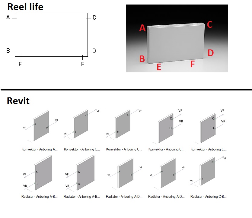
Take a radiator as an example, normally this has 6 connections, but we only use the tow of them.
But as it is now, we need to have a family for each connection type but this its still the same radiator, witch is confusing fore the contractor and the quantities.
I know this has been brought up many times, but IMO it is essential to make modeling of MEP more efficient - particularly for plenum families where you may not know the number or type (O/A or R/A) of connector required in the model.
The other option would be to allow a "face connector" for Ductwork where you can connect multpiple times in different locations on a face and the connector doesnt "turn on" until you connect to it (ie the face could act like the side of a duct and allow taps to connect), would need to allow different systems to connect in this case.
Can you elaborate on why you need to turn connectors on/off for the plenum case? What is the difference between a plenum, and a segment of duct? E.g., you can create a duct with endcaps, and then connect as many taps to it as you need. Is this request more about being able to connect taps to endcaps (perhaps fittings in general?) For the requested plenum case, would connecting taps to fittings suit the need?
Thanks for posting this... can you elaborate on the types of components that would frequently have different number/position, and elaborate a bit on how you'd envision this working?
Thanks for the suggestion... and double thanks for providing an illustration to document your idea.
I do have some questions. I've also provided an image (see below)...
Referring specifically to your 6 port radiator example:
Does VF mean 'in' and VR mean 'out'?
Is it ok to toggle all connectors off?
Could the user have three connectors on?
E.g., could flow come into A, but go out of B and C?
Can the flow direction be reversed?
E.g., instead of coming in A and out B, is going in B and out A a valid configuration?
Are there only specific allowable configurations? (e.g., was the intent to show 10 valid configurations (possibly types), to avoid having the otherwise 15 possible pairings (AB, AC, AD, AE, AF, BC, BD, BE, BF, CD, CE, CF, DE, DF, EF)?
Yes VF = Hydronic Supply in and VR = Hydronic Return out.
No is not ok to toggle all connectors of.
In our country we only have one in and one out so it would not be possible to have 3 connectors on in reel life.
The challenge is that Revit does not allow to create not parameters on multiply parameters, so in Revit it would be possible if one user add an ekstra checkmark in a type.
No the flow can´t change direction, Hydronic Supply is always on top of a radiator.
So the possible types is:
A-B, A-D, C-B, C-D, E-F.
First named connector always representing Hydronic Supply.
Thanks for clarifying.. for E-F, since these are both on the bottom, is there anything preventing these from flowing from F to E in the real world?
Also, would it be possible for you to provide an English link to this 'real world' element...e.g., a catalog page from manufacturer catalog, for example?
You're welcome😊 I'm really the one to say thanks. In Denmark a F-E type would require a special delivery of this. But again it can be done, but we would need to change the type name and a switch the connectors. Aldo this would make no sense at all😊 Why change the flow in a radiator like this? It would not give us more effect in any way.
But since your looking into this, you must have in mind that linking more than 2 connectors must be added as well.
Eg. Floor drains with more than one inlet. I Denmark most floor drains are delivered with one outlet and 3 closed inlets. Then the plumber use the inlets he need, and leve the rest closed. So in that case we need to be able so have Yes/No parameters on all inlet connectors. And to be able so linke them all to the outlet connector. Otherwise Revit creates more than one system. And then the calculation is incorrect😊
""Aldo this would make no sense at all😊 Why change the flow in a radiator like this?"
Good question... I've seen models from users where radiators are piped 'left to right' instead of 'right to left' depending on the direction the supply flow is comming from. I had assumed that for certain components that flow direction doesn't really matter. (In Revit , this ends up being problematic as since they are using the same family with hydronic supply / return connectors, flow ends up confused when connected 'backward'.)
Can you say more about the 'special delivery'? what is different about the FE vs EFcase? I understand what would need to be different in Revit, but what is different in the real world?
"I Denmark most floor drains are delivered with one outlet and 3 closed inlets. Then the plumber use the inlets he need, and leve the rest closed."
Can you provide a sample manufacturer catalog page of such a thing? If I understand correctly, the floor drain could have more than one inlet open? So, in effect, it is acting like a drain and a union, tee, or cross?
Ok😊 A radiator has a front and a back side. At the backside there is prepared for hangers. So E-F means that the hydronic supply is placed at the right side and hydronic return to the left. If you would like an F-E type the hydronic supply is placed to the left and the hydronic return to the right. But again why?
Hi.. thanks for the link. In this case, am I understanding correctly that in addition to the top inlet of the drain, there are three 'side' ports that drainage can collect into the body of this drain, and one outlet at the bottom of the drain?
If one of the three side inlets are not used, how does this get capped? Does the component come with the three side outlets with caps on them, or is this something that the contractor has to order separately a component to cap the inlet?
In the case of the drain, is there a reason someone would care about the on or off status? It just seems like more things to set and potentially mis-configure.
For example, if there was a way for Revit to know that a pipe could connect to these side locations, but if there isn't a pipe connected, don't bother the user... is there a reason you actually care about the on/off status? Or, would it make sense to somehow flag the side pipe connectors in this case as optional?
In other words, why put the burden on the user to turn the connector 'on' of the user wants to (effectively remove the plastic plug), or 'off' if the user wants to put the plug back in place?
Also, is there really a need to link in this case? would there ever be a case where the connectors would NOT be linked for such a drain?
Seems like what you really want is just a drain component that single top inlet (potentially with a load associated with it), along with 0 or more optional side connectors, with a single outlet that collects the load/flow from all the 'used' connectors as a single system. Is there something I'm missing in that definition?
Right, not a physical inlet... but logically, this is where the flow from the drain comes in. Sounds like you want to sum flow from 'me', plus all those things connected in to 'me', and report the total on the 'out'.
The way drains work today, the flow is defined on the outlet connector of the drain, which, is inconsistent with the need to sum flows from the inlets and tabulating them on the outlet.
Got it..
Is there a reason you want to force your user to turn on connectors? What benefit does that provide? In other words, in this scenario, what if the side connectors were 'off' until you connect a pipe to them, then they're implicitly 'on'.. no user interaction required to toggle on/off aside from just connecting the pipe. Is there some reason you want/need that extra step of toggling on before connecting the pipe, or off after disconnecting the pipe when the design changes?

