Snapping or aligning to a sloped surface in section

Snapping or aligning to a sloped surface in section

chughes
Collaborator Collaborator
3,892 Views
24 Replies
Message 1 of 25

Snapping or aligning to a sloped surface in section

chughes
Collaborator
Collaborator

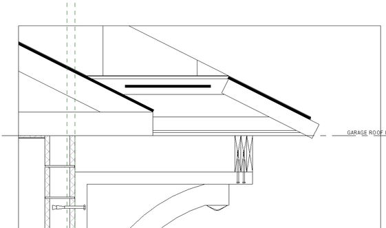
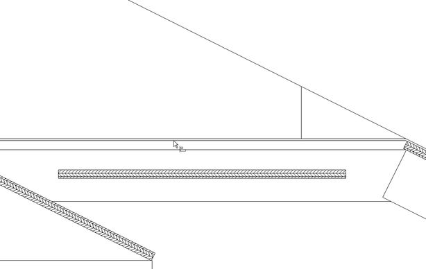
Is it possible to align or snap to a sloped surface that has been cut by a section plane?  IE, I have a section through a roof slope and would like to add 2D detail elements to the section cut.  However, I cannot align my 2D element to the cut through the sloped portion.  Please see below for reference.


Thanks.


ScreenShot470.jpgScreenShot471.jpg

0 Likes
Accepted solutions (1)
3,893 Views
24 Replies
Replies (24)
Message 2 of 25

cbcarch
Advisor
Advisor

Try adding a Reference Plane in the section, then align 2D elements to it.

Cliff B. Collins
Registered Architect The Lamar Johnson Collaborative Architects-St. Louis, MO
0 Likes
Message 3 of 25

chughes
Collaborator
Collaborator

I can draw a reference plane, but still cannot align it with the sliced edges of the roof plane.  Revit seems to ignore those edges?


https://streamable.com/y7eop


0 Likes
Message 4 of 25

barthbradley
Consultant
Consultant

What?! And you are drawing on a workplane? 


...well. there's always AutoCAD. Smiley Wink

0 Likes
Message 5 of 25

chughes
Collaborator
Collaborator

In the video, I am in a section view.  The section cuts through a sloping roof plane.  I would like to align detail elements where the sloping roof plane is cut.  However, I cannot align to the edges where the section cuts through the roof plane.  You can see elements that are available to for aligning to, but when I move over the roof plane elements, they do not highlight and are not available for alignment.


Negative on the workplane question.  This is a simple section cut through a roof.

0 Likes
Message 6 of 25

barthbradley
Consultant
Consultant

Yes, I think I got the picture. I do it all the time without issue. 


What is the detail component you are trying to align? 


@Anonymous wrote:


Negative on the workplane question.


"Negative"? You mean you are not specifying a workplane to draw on? 

0 Likes
Message 7 of 25

barthbradley
Consultant
Consultant

Okay, so I looked at your video. I see the component (plywood) and I see the roof and I see the Ref. Plane.  What I don't understand is the reason for the Ref. Plane in the view. I thought you wanted to align the component to the roof.  Am I misunderstanding? 

0 Likes
Message 8 of 25

ToanDN
Consultant
Consultant

You normally cannot but there is a workaround using Parts.  Unfortunately not everything can be converted to Parts so often you still need to draft ref planes or other drafting elements over and just eyeball them to match the model.


In reality, I have never found myself needing to dimension something like that.  I dimension where the builders can build, not where they look pretty  on the drawings.


See screencast for the workaround I mentioned.


https://knowledge.autodesk.com/community/screencast/656d5d79-e816-41a8-9aa9-8fa3437a2a57


Capture.PNG

Screencast will be displayed here after you click Post.

656d5d79-e816-41a8-9aa9-8fa3437a2a57


0 Likes
Message 9 of 25

barthbradley
Consultant
Consultant

...now we're introducing dimensions and parts into this. What the heck is the issue here?


Edited by
Discussion_Admin

Message 10 of 25

ToanDN
Consultant
Consultant

I added the dimension to demonstrate the ability to snap to the geometry.  Without splitting it to Parts it can't be done. 


Edited by
Discussion_Admin

Message 11 of 25

chughes
Collaborator
Collaborator

The ref plane was in response to @cbcarch suggestion.  I was demonstrating that it did not work.


@ToanDN It isn't something that I need to dimension to, but I do prefer accuracy to eyeballing.  I am a little OCD about.


So the consensus is that Revit ignores cuts through sloped roof assembly surfaces and, to place the detail family, I need to eyeball it.


Purchase cast iron pans.  They are too heavy to throw very far...

Message 12 of 25

barthbradley
Consultant
Consultant

I can usually get it within a gnat's eyebrow by zooming and nudging, and then a "do not scale plans" note protects me from OCD contractors that carry a micrometer with them. Smiley Wink

0 Likes
Message 13 of 25

ToanDN
Consultant
Consultant

@chughes wrote:


I do prefer accuracy to eyeballing.  I am a little OCD about.


You could export the section view to DWG and link it back in the same view, turn off layers you don't need, and snap dimension to the CAD linework.

Message 14 of 25

barthbradley
Consultant
Consultant

...you sure about that @ToanDN?  It's a section through a hip. 

0 Likes
Message 15 of 25

ToanDN
Consultant
Consultant

Whose hip?  Why does it matter?

0 Likes
Message 16 of 25

FAIR59
Advisor
Advisor

When starting a detail line on the edge of a solid all the points are designated as NEAREST to [ ]. When placing an adaptive family all of a sudden the point where  the edge intersects the (section) screen, becomes a "special" point ENDPOINT of [].


 pointOfSection.PNG


Using a helper family (adaptive generic model, containing only 1 adaptive point) you can mark the point where edges intersect the screen plane, and use those points to draw the line(s) you are after. 


pointOfSection02.PNG


0 Likes
Message 17 of 25

Alfredo_Medina
Mentor
Mentor

@Anonymous wrote:


...


So the consensus is that Revit ignores cuts through sloped roof assembly surfaces and, to place the detail family, I need to eyeball it.


...


@chughes No, that is not correct.  Detail components do align to the sloped edge of the roof in a section view. There has to be another issue causing this in your project, or in that detail component that you are using. It is difficult to determine that by just watching the video. 


Alfredo Medina _________________________________________________________________ ______
Licensed Architect (Florida) | Freelance Instructor | Profile on Linkedin
0 Likes
Message 18 of 25

barthbradley
Consultant
Consultant


@Alfredo_Medina wrote:
  Detail components do align to the sloped edge of the roof in a section view. 

That's what I thought @chughes was talking about, but I think what he's talking about aligning a detail item component to the non-sloped (horizontal) line work of the hip roof in the view. Either that, or we're talking about pots and pans. I dunno. 


0 Likes
Message 19 of 25

barthbradley
Consultant
Consultant

@ToanDN wrote:

You could export the section view to DWG and link it back in the same view, turn off layers you don't need, and snap dimension to the CAD linework.


Heck yah, @ToanDN! Works like a charm! Better than a gnat's eyebrow. Smiley Wink

0 Likes
Message 20 of 25

Alfredo_Medina
Mentor
Mentor

Well, what I said above works if the section is perpendicular to the direction of the slope. I see that if the section is at a weird angle, then I see that it's not possible to align and snap to the line of the roof. 


Alfredo Medina _________________________________________________________________ ______
Licensed Architect (Florida) | Freelance Instructor | Profile on Linkedin
0 Likes