Need help with Ceiling pattern with alternating distances - Is it possible?

Need help with Ceiling pattern with alternating distances - Is it possible?

RedMan77
Collaborator Collaborator
7,168 Views
28 Replies
Message 1 of 29

Need help with Ceiling pattern with alternating distances - Is it possible?

RedMan77
Collaborator
Collaborator

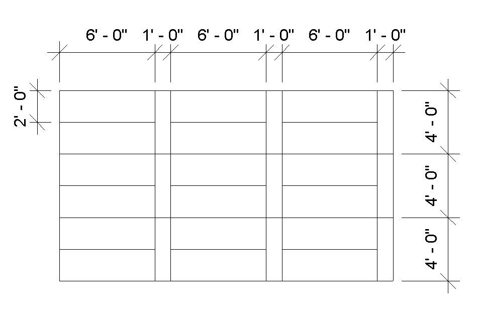
Can anyone please help with a ceiling pattern that is 2'-0" in the X but 2'-0" and then 2'-9" in the Y?  For the whole ceiling it alternates between 2'-0" and 2'-9".  I am going crazy trying to figure this  if its even possible.  Seems it should be too different than a brick pattern.  Trying to create an existing condition in the ceiling and I am coming up against this.  I know I could just draw lines but I am trying to avoid that.  Any assitance is appreciated.  Thanks in advance.

Accepted solutions (2)
7,169 Views
28 Replies
Replies (28)
Message 2 of 29

rosskirby
Advisor
Advisor

Try using Hatch-22.  You can create your own hatch pattern.  Here's the link.

Ross Kirby
Principal
Dynamik Design
www.dynamikdesign.com
Message 3 of 29

RedMan77
Collaborator
Collaborator

Tried that.  Keeps telling me the hatch pattern is too large and when I paste the results in text editor, it doesnt come close to what I need. 


Love that site.  I use the parameter jerk to import numerous parameters into a family at once.

0 Likes
Message 4 of 29

David_W_Koch
Mentor
Mentor
Accepted solution

One line, repeated at a 2'-0" spacing will work for the 2'-0" offsets in the X-direction.  You will need two lines in the Y-direction, repeating at a 4'-9" offset each.  The origin of the second line needs to be 2'-0" in the Y-direction from the origin of the first line.  See attached file.


David Koch
AutoCAD Architecture and Revit User
Blog | LinkedIn
EESignature

Message 5 of 29

RedMan77
Collaborator
Collaborator
Accepted solution

THANKS!!  I think I understand.  I know a little bit about dissecting the values in the pat file but his helps in a big way.  Just one question.  Where does the 4'-9" show up from your response in the file you uploaded.  Did you mean 2'-9"?  Thanks again.  Much appreciated.  Also wanted to thank  for your input as well.

Message 6 of 29

David_W_Koch
Mentor
Mentor

You wanted alternating spacings of 2'-0" and 2'-9".  The offset between members of the same "family" of lines is constant, so one line cannot be spaced at 2'-0" and 2'-9", so you need two parallel line definitions, with a 2'-0" separation in their origin points,  that are spaced at the total of the repeating pattern, which is 2'-0" + 2'-9" = 4'-9" (57 in the PAT file).


Each line in a hatch definition represents a "family" of lines.  The angle of the line is specified in the first field, then the X and Y values of the origin point are specified in the next two fields.  The X offset (offset along the length of the line, regardless of angle; only has meaning for a line that has a dash pattern specified) and the Y offset (offset between members of the family, perpendicular to the direct of the line, regardless of angle) are the fourth and fifth fields.  Optional fields defining pen-down segments (dashes - positive values) and pen-up segments (gaps - negative values) can follow.  For an RCP grid, the lines are continuous, so there are no optional dash fields in the file I attached.


The first line definition is

0,   0,0,   0,57


This creates a horizontal line (0-degree angle) with an origin at 0,0 that has an X-offset along the length of the line of 0 (no dashes, so any number would work) and a Y-offset perpendicular to the length of the line of 57 (4'-9"), so you would get a series of lines running horizontally, 57 units apart.


The second line definition is

0,   0,24,   0,57


This creates a second horizontal line with an origin at 0,24, putting it 24 units (2'-0") away from the first line.  Like the first line, it is continuous, so the X-offset is meaningless and set to 0; the Y-offset is 57 (4'-9"), so this creates a second series of lines that are 57 units apart and 24 units (2'-0") from the previous line of the first line definition and 33 units (2'-9") from the following line of the first defintion line, creating the alternating 2-0" and 2'-9" spacing.


The third line defintion is

90,  0,0,  0,24


Since the spacing of the pattern in the other direction is a constant 2'-0", one line is all that is needed.  The angle is 90, making it a vertical line, with an origin at 0,0.  There is no X-offset along the length of the line, but there is a Y-offset perpendicular between lines of the same family of 24 units (2'-0").


David Koch
AutoCAD Architecture and Revit User
Blog | LinkedIn

EESignature

Message 7 of 29

RedMan77
Collaborator
Collaborator

AHA!!!  Got it. Thanks for the clarification.  Makes total sense. You Rock!

0 Likes
Message 8 of 29

Anonymous
Not applicable

David, 


I'm having a similar problem where I would need a ceiling pattern that goes 2' x 6', 2' x 6', 2' x 6', 1' x 6'.


I tried modifying your .pat file but failed miserably, please help.


Thank you.

0 Likes
Message 9 of 29

David_W_Koch
Mentor
Mentor

You will need four horizontal lines. The angle for each of these four lines is 0, so the first number of each line is 0.  The origin points for each line will have an X value of 0 (second number) and Y values of 0, 30, 60 and 78 respectively.  The lines are continuous, so the fourth number does not matter and is set to 0.  The total pattern length is 9'-0" (108), so the fifth number for each of those lines would be 108.  You did not specify, so I assume that in the vertical direction, you wanted lines spaced at 2'-0" (24).  Here are the lines in the hatch definition: 

0,  0,0,      0,108
0,  0,30,     0,108
0,  0,60,     0,108
0,  0,78,     0,108
90, 0,0,      0,24


See the attached file.


David Koch
AutoCAD Architecture and Revit User
Blog | LinkedIn
EESignature

Message 10 of 29

Anonymous
Not applicable
Thank you so much David!
0 Likes
Message 11 of 29

RedMan77
Collaborator
Collaborator

Lol.  Just realized I was the originator of this post.  Your original solution was perfect.  Now I have an new issue where the ceiling grid is quite odd. I have been trying to edit you pattern file in a way that is similar to this post I found.  I havent figured out how to make an alternating pattern in both the X & Y.  Using your pattern file I made my pattern 24", then 30", 24" then 30" and so on in the Y direction.  Having trouble figuring how to do this in the X direction.  In the X direction I need an alternating pattern of 24", 30", 24", 30", etc.


0, 0,0, 0,108
0, 0,24, 0,108
0, 0,54, 0,108
0, 0,78, 0,108
90, 0,0, 0,24


Any help would be appreciated.  Thanks.

0 Likes
Message 12 of 29

RedMan77
Collaborator
Collaborator

Figured it out.  I wanted an alternating grid of 24", then 30" in both the X and Y.


*Ceiling_24xCustom, 2-0 x 2-6 2-0 2-6 and 1-6
;%TYPE=MODEL;
0, 0,0, 0,108
0, 0,24, 0,108
0, 0,54, 0,108
0, 0,78, 0,108
90, 0,0, 0,108
90, 24,0, 0,108
90, 54,0, 0,108
90, 78,0, 0,108

0 Likes
Message 13 of 29

David_W_Koch
Mentor
Mentor

If your pattern just alternates 24" and 30" spacings in both directions, then


0, 0,0, 0,54
0, 0,24, 0,54
90, 0,0, 0,54
90, 24,0, 0,54

for the line definitions should be sufficient.  Your pattern works, but has two extra lines in each direction that are not needed.


David Koch
AutoCAD Architecture and Revit User
Blog | LinkedIn
EESignature

0 Likes
Message 14 of 29

RedMan77
Collaborator
Collaborator

I dont see extra lines in my ceiling.  This is exactly the "As-"Built" condition I am trying to record.  Are you trying to say I am overcomplicating the code?  Trying to understand.  Thank you very much for your input.

0 Likes
Message 15 of 29

David_W_Koch
Mentor
Mentor

There are no extra ceiling grid lines generated by your pattern; there are just extra lines being defined in your pattern.  Your pattern repeats every 54" in both directions.  My pattern defines two lines in each direction, each offset 54".  You set up your pattern with a 108" repeat, so you needed to define two extra lines in each direction.


Same end result, just with more lines to code and track in the hatch pattern definition.


David Koch
AutoCAD Architecture and Revit User
Blog | LinkedIn
EESignature

0 Likes
Message 16 of 29

RedMan77
Collaborator
Collaborator

Gotcha.  Thanks for the clarification. 

0 Likes
Message 17 of 29

Anonymous
Not applicable

I need help creating a grid pattern of 3'x11", 2'-1" and 3'-11" x 3'-0"

I tried editing the pat file provided but unsuccessful  see below


*Custom Ceiling
;%TYPE=MODEL;
00, 0,0, 0,83
00, 0,36, 0,83
90, 0,0, 0,72
90, 0,25, 0,72


Thanks for your help

0 Likes
Message 18 of 29

David_W_Koch
Mentor
Mentor

@Anonymous


Apologies for the delayed response;  I am a bit behind in my reading of this forum. In the future, use an "@" mention as I did above to send that person a notification email calling attention to your post.  I m not in front of Revit right now to test this, but I believe that switching the 0 and 25 as shown below should give you the pattern you want.  You may have already worked that out by now.


*Custom Ceiling
;%TYPE=MODEL
00, 0,0, 0,83
00, 0,36, 0,83
90, 0,0, 0,72
90, 25,0, 0,72


David Koch
AutoCAD Architecture and Revit User
Blog | LinkedIn
EESignature

0 Likes
Message 19 of 29

Anonymous
Not applicable

Hi @David_W_Koch,


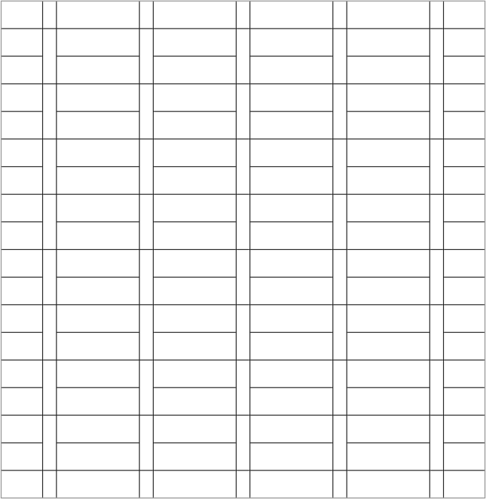
I'm currently working on a ceiling grid pattern that has 2 parallel 2'x6' with a  1'x4' grid perpendicular to it.

I tried to wrap my head around the discussions but I think the solution to mine can be somewhat similar but more complicated as it is. Can you help me with this, please? I attached an image of what I'm trying to achieve.

Thanks. 

2x6x1 ceiling grid.JPG

0 Likes
Message 20 of 29

David_W_Koch
Mentor
Mentor

Try this:

;%VERSION=3.0
;%UNITS=INCH

*ClgGrid_2x6_1x4, Grid with stacked 2'x6' panels alternating with 1'x4' panels
;%TYPE=MODEL

0,    0,0,   0,48
0,    0,24,  0,48,  72,-12
90,   0,0,   0,84
90,  72,0,   0,84

Use Notepad to save that to a file called ClgGrid_2x6_1x4.pat (make certain the extension is pat, and not txt).  If you would prefer a different name, change ClgGrid_2x6_1x4 in the text above to your preferred name and use that as the name of your file (with a pat extension).2019-08-01_CustomClgGridHatchPatternResult.png


David Koch
AutoCAD Architecture and Revit User
Blog | LinkedIn
EESignature