Angle Parameter & 2 Length Parameters

Angle Parameter & 2 Length Parameters

Anonymous
Not applicable
7,771 Views
15 Replies
Message 1 of 16

Angle Parameter & 2 Length Parameters

Anonymous
Not applicable

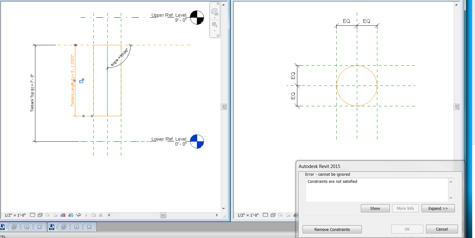
Question: Does anyone know how to successful do an angle parameter from the vertical?


Issue: I cannot get the angle to lock to the shape using a reference line or reference plan. It makes me unconstrain my other successful lenth parameters.


Goal: I am trying to add tiebacks to my Revit project. Refer to the "Column & Tieback" file. For each tieback, I have the Elevation it starts at (y), the angle from the vertical/column (theta), and the length of each tieback (L).


Attachments:

Tieback: Family I started using the "Structural Column Template." I can do the 2 length parameters, but not sure how to do the angle parameter.

Column: The project I am trying to add the tiebacks to.

Column & Tieback: This is what I am trying to accomplish.


0 Likes
Accepted solutions (1)
7,772 Views
15 Replies
Replies (15)
Message 2 of 16

rodrigo.bezerra
Advisor
Advisor
Reference planes won't work for angle parameters. Do it with Reference Lines.

Regards!

Rodrigo Bezerra

EESignature

0 Likes
Message 3 of 16

Anonymous
Not applicable
Thanks for replying.
I tried both and it's not working.
How do I tell the shape to align to the reference line? Everything I try, fails.
0 Likes
Message 4 of 16

rodrigo.bezerra
Advisor
Advisor
I would do the shape as a sweep, and constraint the sketched path to the
reference line. Extrusions are complicated to constraint in this case.

Rodrigo Bezerra

EESignature

0 Likes
Message 5 of 16

Anonymous
Not applicable

Thanks.

Now the length (L) parameter isn't wokring.

Is there a problem with two length parameters working with an angle?

Or is there a way to make the reference line a parameter length?

0 Likes
Message 6 of 16

Keith_Wilkinson
Advisor
Advisor

Trying creating your extrusion as a sub family using a face based template.  


Load this into your family and then place On Face using the place on workplane option and 'pick' for the placement plane.


I've uploaded a short screencast showing how this works with a door leaf but the principle will be the same for what you are trying to do.


"Give a man a fish and you feed him for a day; teach a man to fish and you feed him for a lifetime."
Maimonides
0 Likes
Message 7 of 16

RDAOU
Mentor
Mentor

@Anonymous


They do but not if they are constraining the reference line. The Length parameter should constrain the tieback/element not ref line...The constraints are not satisfied because of the when you change the angle to rotate Tieback  the length of the reference line will need to change while it is aligned at one end (the center of rotation) and locked. 


In your family the ref line can not change its length when it rotates so Constraints not satisfied

YOUTUBE | BIM | COMPUTATIONAL DESIGN | PARAMETRIC DESIGN | GENERATIVE DESIGN | VISUAL PROGRAMMING
If you find this reply helpful kindly hit the LIKE BUTTON and if applicable please ACCEPT AS SOLUTION


Message 8 of 16

Anonymous
Not applicable
Thanks.
What Family Template are you using?
The structural column template only allows me to place on vertical or slanted.
0 Likes
Message 9 of 16

rodrigo.bezerra
Advisor
Advisor
You can start the sub component as a generic model and change it's category
later.

Rodrigo Bezerra

EESignature

0 Likes
Message 10 of 16

Keith_Wilkinson
Advisor
Advisor

@Anonymous I started with a generic face based family template - as @rodrigo.bezerra has said, you can change the category to what you need by clicking on the Family Category and Parameters button on the Create Ribbon - there you should see structural columns.


"Give a man a fish and you feed him for a day; teach a man to fish and you feed him for a lifetime."
Maimonides
Message 11 of 16

Anonymous
Not applicable

All, nothing is working.


The best I've got is attached, but:

1. I cannot recreate it

2. the length parameter isn't accurate. It should be dependent on the angle.


I've attached my Familily. I am using Revit 2015.


If someone can walk me through this step-by-step, that'll be great.

0 Likes
Message 12 of 16

RDAOU
Mentor
Mentor
Accepted solution

@Anonymous


I just fixed what you had the way I understood you post...I'm not sure if this is how you want it to behave

  1. You need first to fix the rotation angle by locking it's (the ref. line) end (center of rotation) to two ref planes - I assumed it is the top
  2. First I unlocked the reference line from whatever you had it locked to
  3. Extend the Center-(front back) ref plane
  4. Lock end of ref line to the Center-(front back) and the horizontal reference plane you had on top (this fixes the center of rotation to that point)
  5. Re-set the Tieback_Length parameter end point to end point of the ref. line (which is the path of the sweep)
  6. re-set Tieback_height from the ref level to the end point of the Reference line (center of rotation end)
  7. I added a radius parameter for the tieback

PS: the naming of parameters shouldn't include ( ) ] [ : shuch characters


Seems to flex ok now...


I wasn't sure what you meant by Length should be dependent on the angle (but to do that you need to triangulate) - from where I see it you have angle B parameter "Angle"...and you need to calculate h= Tieback_Length which I assume would be the hypotenuse based on that angle and where the tieback ties to...To do that you need to know where it ties to (Segment AC = b)


If thats what you need then you need to add another paramete for Tiepoint_Base (Dimension between vertical ref. plane and bottom end of refline) and add formula the Tieback_Base and Tieback_Length

Tieback_Base = Tieback_Top * (sin(Angle) / cos(Angle))


Then


Tieback_Length =  Tieback_Base / sin(Angle)


That should be fairly easy to do now that it flex ok...in this case you just enter the angle and the height

Trigonometry_triangle.png


YOUTUBE | BIM | COMPUTATIONAL DESIGN | PARAMETRIC DESIGN | GENERATIVE DESIGN | VISUAL PROGRAMMING
If you find this reply helpful kindly hit the LIKE BUTTON and if applicable please ACCEPT AS SOLUTION


Message 13 of 16

Anonymous
Not applicable

@RDAOU


Thank you! 


In the video for the "Select Profile" step, what did you do after you double-clicked on the sweep and selected "Select Profile"?

Are you holding CRTL with TAB or seperate? I've tried, but it doesn't do anything. Are you clicking the mouse during the CRTL + TAB?


Thanks.

0 Likes
Message 14 of 16

RDAOU
Mentor
Mentor

@Anonymous


CTRL + TAB is to switch between the view windows (was looking for the 3D View)... it doesn't do a thing if you have just one view window open


The question is ... was that what you needed? or What you were asking about?

YOUTUBE | BIM | COMPUTATIONAL DESIGN | PARAMETRIC DESIGN | GENERATIVE DESIGN | VISUAL PROGRAMMING
If you find this reply helpful kindly hit the LIKE BUTTON and if applicable please ACCEPT AS SOLUTION


0 Likes
Message 15 of 16

Anonymous
Not applicable
So far so good!
I will let you know (for sure) as soon as I execute everything in the video.

0 Likes
Message 16 of 16

Anonymous
Not applicable

Thank you everyone for your input!


It seems we finally got this figured out!

0 Likes