Announcements

Starting in December, we will archive content from the community that is 10 years and older. This FAQ provides more information.

Community
Inventor Forum
Welcome to Autodesk’s Inventor Forums. Share your knowledge, ask questions, and explore popular Inventor topics.
cancel
Showing results for 
Show  only  | Search instead for 
Did you mean: 

Tube and Pipe style will not save.

16 REPLIES 16
SOLVED
Reply
Message 1 of 17
Anonymous
2485 Views, 16 Replies

Tube and Pipe style will not save.

Hi,


New to Inventor. Have been working through tutorials from the "tutorial archive" section of Inventor 2017 Help. This archive actually takes you to Inventor 2014 help. In the Tube and Pipe tutorials I am working on the one titled Self-draining Lines. Have followed the tutorial exactly except for setting up a new read/write library. I work in a Vault environment so I used our default read/write library. When I get to the section to create the self draining style i keep running into a problem. I hit the save button on the Tube and Pipe Styles dialog box and the computer spins for a few moments like its saving then...nothing. the save button is still available and is not grayed out. If I hit the Close or X buttons it asks me if I want to save edits. selecting yes gives you the exact same result as before. Unable to close dialog box unless I select No to saving the edits. If I un-check the Self Draining box and don't have the custom elbow I can save the new style just fine, so the problem seems to be with the custom elbow created earlier in the tutorial. I have deleted the elbow several times from content center, re-authored it and re-published it to make sure it is absolutely correct but to no avail. I have noticed that on some occasions when I go the re-author that the nominal size has changed from 3/4 to.9 in. not every time and it seems to happen randomly. Anyone have a clue as to what is happening here? Or how to correct it?


Thank you

16 REPLIES 16
Message 2 of 17
Mark.Lancaster
in reply to: Anonymous

@Anonymous


To me is sounds like you authoring for the custom self draining elbow is not correct.   Can you provide the ipart factory that you used to author this elbow to the content center.   @cbenner any other thoughts?

Mark Lancaster


  &  Autodesk Services MarketPlace Provider


Autodesk Inventor Certified Professional & not an Autodesk Employee


Likes is much appreciated if the information I have shared is helpful to you and/or others


Did this resolve your issue? Please accept it "As a Solution" so others may benefit from it.

Message 3 of 17
cbenner
in reply to: Mark.Lancaster


@Mark.Lancaster wrote:

@Anonymous


To me is sounds like you authoring for the custom self draining elbow is not correct.   Can you provide the ipart factory that you used to author this elbow to the content center.   @cbenner any other thoughts?


@Anonymous, Hello!


I agree with @Mark.Lancaster, it sounds like an authoring problem with your elbow.  It could also be a units mis-match between some of the fittings in your style and the conduit specified.  In addition to a look at your ipart as Mark suggested, it would also help to see screen shots of the authoring screen for this part and screen shots of the T&P style you are trying to create.  If possible, a video of the work flow might help diagnose it as well.


Message 4 of 17
Anonymous
in reply to: Anonymous

The custom elbow is not an ipart. it is a single part, available in 1 size only. This is explicitly stated in the tutorial. please see line ten below from the tutorial.


Create the Self-draining Style


We now create a self-draining style using the elbow we authored and published.

  1. On the ribbon, click Environments tab Begin panel Tube and Pipe .
  2. In the Run Assembly File Name field of the Create Run dialog box, type SD Run.
  3. Click OK.
  4. Click Pipe Run tab Manage panel Tube and Pipe Styles .
  5. In the style browser of the Tube & Pipe Styles dialog box, expand the Rigid Pipe with Fittings node.
  6. Right-click the ASME B36.10M-ASME B16.11 – Steel Threaded Pipe style, and select Copy. You modify this copy to create the self-draining style.
  7. Right-click ASME B36.10M-ASME B16.11 – Steel Threaded Pipe_Copy(1), and select Active to make the copied style active.
  8. Right-click the style, and select Edit.
    Note: Instead of using the context menu, you can use the commands at the top of the dialog box to manipulate the style.
  9. On the General tab, select the Self Draining option. When you select the Self Draining style type, the Elbow Custom component is added to the component list. The icon indicates that the component is required and has not yet been specified from the Content Center.
  10. Because the elbow you published earlier is not an iPart, it is available in one size only. In the Diameter box, set the Nominal Diameter to 3/4 in.
  11. Right-click Elbow Custom, and select Browse. It accesses components in the Content Center. It can take a few moments.
  12. When the Library Browser dialog box activates, select the elbow (self-draining_elbow) you published earlier.
  13. Click OK.
  14. In the Name field of the Tube & Pipe Styles dialog box, replace the _Copy(1) portion of the default style name with SD Temp.
  15. Click Save.
Message 5 of 17
Mark.Lancaster
in reply to: Anonymous

@Anonymous


For me I think that's wrong from my experience with routed system..  Authored piping components even if its a single size should still be an iPart.   @cbenner your thoughts?


Update:  @Anonymous..  If you really want to learn routed system you should be speaking to @cbenner and asking for his information and not learning for these tutorials.  Smiley Wink

Mark Lancaster


  &  Autodesk Services MarketPlace Provider


Autodesk Inventor Certified Professional & not an Autodesk Employee


Likes is much appreciated if the information I have shared is helpful to you and/or others


Did this resolve your issue? Please accept it "As a Solution" so others may benefit from it.

Message 6 of 17
Anonymous
in reply to: Anonymous

sorry that last one got sent twice. the part was authored as below (many, many times)


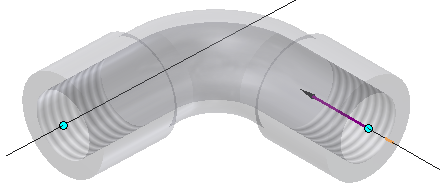
Author the Elbow


The custom fitting is the definitive component in a self-draining style. The custom fitting determines the slope angle and is the functional difference between a self-draining style and a style that is not self-draining.

Authoring prepares a part for publishing to the Content Center by adding specific data to the model. Use Tube and Pipe Authoring to complete the authoring process before publishing to Content Center.

  1. Open self-drain_elbow.ipt, located in the Tube & Pipe directory.

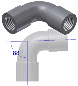
    This elbow was created so that there are 88 degrees between connection axes. The elbow is ready for authoring and publishing. No further design work is needed.

  2. On the ribbon, click Manage tab Author panel Tube and Pipe .
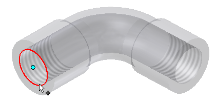
  3. To set the connection point for the first connection, select the circular edge.
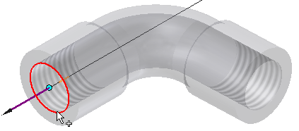
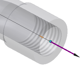
  4. Click the Axis selector.
  5. Select the circular edge again.
  6. Set the Nominal Size to 3/4.
  7. Change your selection to Connection Number 2 .
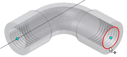
  8. Select the other circular edge to set this connection point.
  9. Click the Axis selector.
  10. Select the circular edge again.

    Flip the direction of the connection vector so that it points out and away from the elbow. Both connection vectors point out and away from the fitting.

    The Angle field shows the angle between the two axes. In this example, 88 degrees is used.

  11. Set the Nominal Size to 3/4.
  12. In the Engagement area, select Distance from the Max pull-down menu, and enter 1 as the value.
  13. Ensure that the Min value is set to 70 (for % of Max.).
  14. Click OK.

    A message indicates that the authoring was successful.

Message 7 of 17
Anonymous
in reply to: Mark.Lancaster

thank you for the info. hopefully cbenner can get me on the right track!:

Message 8 of 17
salariua
in reply to: Anonymous

I can't see anything wrong with your elbow except that it's a single part and I would make it a family for your sake when you need a different size but it will work.


I just did a test, created, authored, published and used a single part elbow (no ipart table) and I can use it in routed systems. Did you specify the gravity direction? Do you have all the fields filled in on the Rules tab? min, max, increment?


Try the one attached. Publish it to content center and use it along with this pipe and 90deg elbow


ANSI/ASME B36.19M Pipe with Threaded Ends

ASME b16.3 90 Deg Elbow


170516-01.gif

Adrian S.
blog.ads-sol.com 

AIP2012-2020 i7 6700k AMD R9 370
Did you find this reply helpful ?
If so please use the Accepted Solutions or Like button - Thank you!
Message 9 of 17
cbenner
in reply to: Mark.Lancaster

Careful @Mark.Lancaster... I've never done a self draining elbow.  I hear they can be real buggers though.  I think that if @Anonymous can get this to work he may be our go to guy on the topic!  LOL


Message 10 of 17
cbenner
in reply to: Anonymous

@Anonymous


So, how about screen shots of the Tube & Pipe style creation window?  I still wonder if there could be a units mismatch somewhere.  Usually when you get the T&P style that won't save, it is an error in one of the fittings or conduit being assigned to that style.  The debug is to work your way through each one until you figure out which one is causing you fits... and then open that part to see what about it may be wrong.

Message 11 of 17
Anonymous
in reply to: salariua

This works perfectly. created the new style no problems. Thanks, now to find out where the incompatibility is when using the elbow and selections from the tutorial. It's nice to know it doesn't seem to be operator error!

Message 12 of 17
Anonymous
in reply to: cbenner

I just closed Inventor, shutdown and restarted my system and re-opened Inventor. tried the tutorial path again. When I hit the save button this time I get a pop-up dialog box as shown in the attachment. Yesterday it simply refused to save but there was no dialog box. I must have hit the "Don't show this message again this session" button early on in the process without realizing what I was doing.


The message say it can't find a conduit or fitting in content center. 


Does this message confirm your suspicions?


If so I am not quite sure how to go about hunting for the item responsible units incompatibility problem.

Message 13 of 17
Anonymous
in reply to: salariua

Ok, have been trying a few things. The tutorial has you make a copy of an existing style, edit and rename it to create the new style. since this isn't working I decided to try creating the style by clicking the "new" option instead of copying and editing, as @salariua had me do in his suggestion. I started with the minimum required, a pipe and a 90 deg elbow, I used exactly the same families for these as are used in the pre-existing style "ASME B36.10M-ASME B16.11 - Steel Threaded Pipe". And strangely got the same error, that it couldn't find a conduit or fitting. Now if I copy the pre-existing style and make a new style it works perfectly unless I include the self drain elbow, so those two things should work fine together since they do in the pre-existing style and in a copy of it. I went digging in the family table an found that the 90 deg elbows have no unit marks in the ND column if they are a fractional size but full inch sizes have an inch " symbol after them. That didn't seem correct. I went back into my project and turned off our companies custom library in the tutorial project I was using so only standard content center libraries were in the project. looked again at the table for the 90 deg elbows and this time they show no inch " symbol in the ND column. I tried creating the style again using the new button and this time it worked fine. Of course I can't include the self-drain elbow because I have removed the only read/write library I have available from my project. We use a Vault configuration with a single shared project and that project uses a single custom content center library. When I set up my tutorial project I was including that library plus all the standard read only ones. So it would seem that the problem lies in our custom content center library somehow. Perhaps when it was created and these families were copied in the units designation got messed up? Not sure exactly how to correct. (do I re-copy the family into our custom library or just go in and edit the ND column?)


What are your thoughts on this?

Message 14 of 17
Anonymous
in reply to: cbenner

I got it to work. but in a really ugly and inelegant fashion. I left the custom library out of the project. created the new style with 90 and 45 degree elbows pipe and couplings all the same as the pre-existing style. Saved it and made it active. went back into manage projects. Added the custom library back into the project. Then I went into Tube and Pipe styles, selected the style and hit edit. Added the custom self draining elbow and saved the edit. Seems to have worked perfectly. Style is now saved and active. Apparently when creating a style and using a part from a custom library it will then check for and default to that custom library for other component families in the style if they are in that library. Which would explain why I got the error when trying to add the custom elbow but not when I did a straight copy of the existing style. But it must not do this when editing an existing file. Doesn't quite explain why I couldn't create the style using the new button with just the pipe and 90 deg elbow. unless using new defaults to custom libraries first as well. Seems I have for the the most part narrowed down the culprit. Is there anything I am missing? Still not sure of the best way to correct the problem in our custom library. Any suggestion on that front would be appreciated.

Message 15 of 17
salariua
in reply to: Anonymous


@Anonymous wrote:

This works perfectly. created the new style no problems. Thanks, now to find out where the incompatibility is when using the elbow and selections from the tutorial. It's nice to know it doesn't seem to be operator error!


Out of the 6 messages posted after mine, this is the only one I got a notification for. I didn't even get a mail notification when you called me out with @salariua


The conclusion from your posts I got:

"if you copy a family to your custom library then Inventor will default to your custom family and not the original, standard library"


That is correct and you will 9/10 want to use your custom library and if you don't then you need to remove it from the project.


Adrian S.
blog.ads-sol.com 

AIP2012-2020 i7 6700k AMD R9 370
Did you find this reply helpful ?
If so please use the Accepted Solutions or Like button - Thank you!
Message 16 of 17
Anonymous
in reply to: salariua

@cbenner  @salariua


Gentlemen,


Thank you very much for your assistance. This tutorial only taught me a little about tube and pipe. But it ended up teaching me a lot about how content center libraries function.

Message 17 of 17
cbenner
in reply to: Anonymous

Can't find what you're looking for? Ask the community or share your knowledge.

Post to forums  

Autodesk Design & Make Report