Community
Inventor Forum
Welcome to Autodesk’s Inventor Forums. Share your knowledge, ask questions, and explore popular Inventor topics.
Turn on suggestions
Auto-suggest helps you quickly narrow down your search results by suggesting possible matches as you type.
Reply
Topic Options
- Subscribe to RSS Feed
- Mark Topic as New
- Mark Topic as Read
- Float this Topic for Current User
- Bookmark
- Subscribe
- Printer Friendly Page
Message 1 of 12
Anonymous
668 Views, 11 Replies
02-27-2019
02:02 PM
- Mark as New
- Bookmark
- Subscribe
- Mute
- Subscribe to RSS Feed
- Permalink
- Report
02-27-2019
02:02 PM
3D Sweep Error
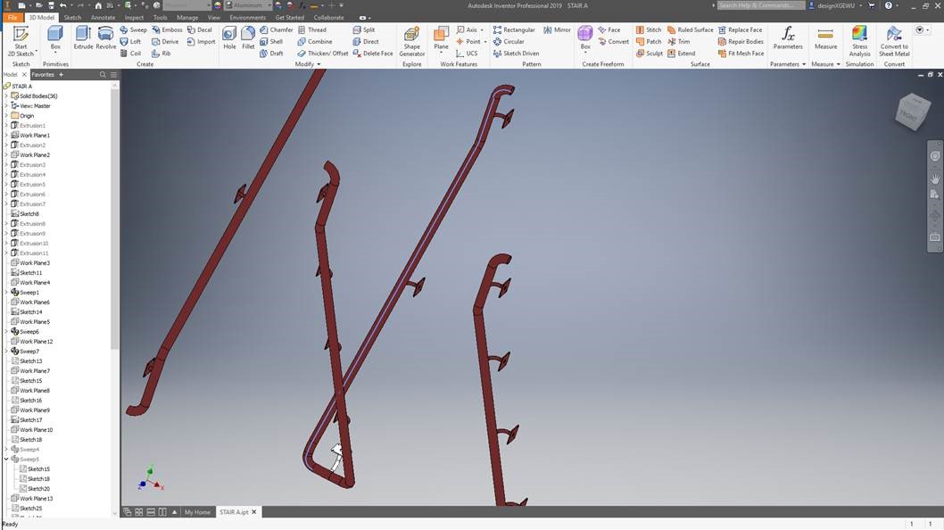
I have one sweep in my model where the Inventor software is changing from a parametric circle into a curve and adding a spine to the model. It is SWEEP5 in the attached model. Can anyone explain why? Tech support at the AutoDesk reseller doesn't know. I have been using AutoCAD for 25 years & SW for 15 years. I have been using Inventor for 3 months and so far not impressed.
11 REPLIES 11
Message 2 of 12
02-27-2019
02:25 PM
- Mark as New
- Bookmark
- Subscribe
- Mute
- Subscribe to RSS Feed
- Permalink
- Report
02-27-2019
02:25 PM
Sweep5 profile is the end of another piece of railing. The sketch is not parametric, it is simply reference geometry. You need to explain your issue better because from what I see, the sweep is acting normally. By the way, sometimes modeling in a new application is a matter of attitude, give Inventor a chance, it has some good features.
"If you find my answer solved your question, please select the Accept Solution icon"
John Hackney
Retired
Beyond the Drafting Board

Message 3 of 12
02-27-2019
02:28 PM
- Mark as New
- Bookmark
- Subscribe
- Mute
- Subscribe to RSS Feed
- Permalink
- Report
02-27-2019
02:28 PM
Pull your End of Part marker up just after Sweep 4. When I measure the angle between the first line segment in Sketch 18, and the face at the end of Sweep 4, I get 89.9947.... deg, not 90 degrees. This means your sweep profile in Sketch 20 isn't perpendicular to your sweep path, so your sweep isn't going to be perfectly round, hence the extra edge. Correct the issue and the edge goes away.

Message 4 of 12
02-27-2019
03:37 PM
- Mark as New
- Bookmark
- Subscribe
- Mute
- Subscribe to RSS Feed
- Permalink
- Report
02-27-2019
03:37 PM
Thanks for seeing that.
Why the software has arbitrarily decided to terminate Sweep4 in that manner when the sketch shows it clearly requiring to terminate at 90deg. Unreal.
Message 5 of 12
02-27-2019
03:42 PM
- Mark as New
- Bookmark
- Subscribe
- Mute
- Subscribe to RSS Feed
- Permalink
- Report
02-27-2019
03:42 PM
This is not my first experience with an Autodesk products. Even the tech support at the reseller commented that the software is not perfect. Hence my "attitude" when the software just does it's own thing arbitrarily.
Message 6 of 12
02-27-2019
04:19 PM
- Mark as New
- Bookmark
- Subscribe
- Mute
- Subscribe to RSS Feed
- Permalink
- Report
02-27-2019
04:19 PM
Hi Matthew,
With your extensive modeling experience in AutoCAD and SWX, I am surprised to see the imperfect conditions in the sketches. Look at Sketch15 and Sketch18. There are overlapped segments. Sketch17 and Sketch18 also overlap. Sketch17 itself has a gap between the arc and the straight segment toward the end.
I guess you tried to create a continuous curve but somehow you did not see the gap. Then you create other sketches to continue to sweep. These issues in the sketches preventing Inventor from creating meaningful geometry. If you know any CAD program capable of creating usable geometry based on these sketches, please let me know.
Many thanks!
Johnson Shiue (johnson.shiue@autodesk.com)
Software Test Engineer
Message 7 of 12
02-27-2019
04:30 PM
- Mark as New
- Bookmark
- Subscribe
- Mute
- Subscribe to RSS Feed
- Permalink
- Report
02-27-2019
04:30 PM
I am surprised by the tone in a response like yours from an AutoDesk employee!
Maybe you can demonstrate how a user can constrain geometry in a 3D sketch to geometry contained in two separate 2D sketches without having to project the geometry into the 3D sketch?
Overlaps in sketches have zero to do with a software arbitrarily deciding to skew the end face of a sweep to 89.9995deg?
Message 8 of 12
02-27-2019
04:58 PM
- Mark as New
- Bookmark
- Subscribe
- Mute
- Subscribe to RSS Feed
- Permalink
- Report
02-27-2019
04:58 PM
Hi Matthew,
If I offended you in any shape or form, I apologize. My reply was specific to your original posting. Please read your own posting and you will understand how I felt.
Creating a 3D sketch is indeed not easy. Based on your part, you have a bunch of pre-defined 2D planes and you are using multiple 2D sketches to create 3D path. It is a common workflow. There is nothing wrong with that. But, you need to make sure each plane is defined properly and the connection between points are correctly made.
Another common technique is to set up the workplanes. Then create one 3D sketch and constrain the sketch using the workplanes. In this way, you can ensure that the lines are continuous. The reason why the profile plane is slightly off is because the end of the arc in Sketch17 is not 90 degree (slightly stop short). As a result, the end cap face at Sweep4 is not perpendicular to Sketch18. These imperfections will cause downstream failures sooner or later.
I reuse some of the 2D Sketches to create the 3D Sketch. An arc of 2.25 (Sketch17) cannot be made in the 3D Sketch, possibly due to slightly misaligned workplanes. Please see attached part. The sweep looks much smoother now.
Many thanks!
Johnson Shiue (johnson.shiue@autodesk.com)
Software Test Engineer
Message 9 of 12
02-28-2019
02:15 AM
- Mark as New
- Bookmark
- Subscribe
- Mute
- Subscribe to RSS Feed
- Permalink
- Report
02-28-2019
02:15 AM
@Anonymous wrote:
Even the tech support at the reseller commented that the software is not perfect.
I use SolidWorks and Inventor every day.
This is not a software issue- if you Attach your SolidWorks example (or any other CAD) I can prove to you the geometrically logical solution that will work in any CAD.
-----------------------------------------------------------------------------------------
Autodesk Inventor 2019 Certified Professional
Autodesk AutoCAD 2013 Certified Professional
Certified SolidWorks Professional
Message 10 of 12
02-28-2019
09:00 AM
- Mark as New
- Bookmark
- Subscribe
- Mute
- Subscribe to RSS Feed
- Permalink
- Report
02-28-2019
09:00 AM
I re-read my post numerous times John and do not see what is so offensive to you. If I am not impressed by a software after three months of using it then that is what it is.
I measure my reference points relative to WCS and there is no quantifiable mis-alignment in my work planes.
How is it that I can create 3D sketch with constraints to sketches made on work planes without projecting redundant geometry into the 3D sketch?
Message 11 of 12
02-28-2019
09:26 AM
- Mark as New
- Bookmark
- Subscribe
- Mute
- Subscribe to RSS Feed
- Permalink
- Report
02-28-2019
09:26 AM
@Anonymous wrote:
Overlaps in sketches have zero to do with a software arbitrarily deciding to skew the end face of a sweep to 89.9995deg?
The software didn't "arbitrarily decide" to do anything. Open up your Sketch 17. It says "1 dimensions needed", and you can freely drag the end of the arc away from the line, like this:

Therefore, that arc is not a perfect 90 degree arc, hence why the face at the end of that sweep is not perfectly orthogonal, hence the spine you're seeing in Sweep5. If you create a vertical constraint between the lower endoint of the arc and the centerpoint of the arc, the spine on Sweep 5 goes away. Some downstream issues pop up but I'm sure you can diagnose those.
Most of your sketches are fully constrained, so you know what you're doing. The red flag to you should have been the lack of the thumb-tack icon on Sketch 17 that means "fully constrained". Most of your sketches have it, but some don't. I would check those as well.
Message 12 of 12
02-28-2019
02:40 PM
- Mark as New
- Bookmark
- Subscribe
- Mute
- Subscribe to RSS Feed
- Permalink
- Report
02-28-2019
02:40 PM
Hi Matthew,
Your sentiment to the product and my feeling to your posting are totally irrelevant to the issues we are discussing. You have your opinions and I have mine. Let's maintain mutual respect.
Regarding how to constrain 3D lines to workplanes, it is not difficult. You can use Coincident constraint to snap a line (the entire line) to a workplane. There are indeed unfavorable conditions in the part. There should be better workflows to do that in Inventor (either in series of 2D sketches or entirely in 3D or mix of the two).
Inventor forum is quite active. We have experts around the world reviewing threads and helping resolve various requests. The accumulated Inventor experience is stunning (Expert Elites alone probably have 1000+ years of Inventor usage). We are here to help. You are more than welcome to join any discussion.
Many thanks!
Johnson Shiue (johnson.shiue@autodesk.com)
Software Test Engineer
Reply
Topic Options
- Subscribe to RSS Feed
- Mark Topic as New
- Mark Topic as Read
- Float this Topic for Current User
- Bookmark
- Subscribe
- Printer Friendly Page
Forums Links
Can't find what you're looking for? Ask the community or share your knowledge.
Post to forums
