Tapered Extrude Problem

Tapered Extrude Problem

mcobb
Advocate Advocate
4,265 Views
21 Replies
Message 1 of 22

Tapered Extrude Problem

mcobb
Advocate
Advocate

I've probably been working on this extrude problem for several hours now. I'm starting to worry I'm not going to come up with a valid tapered extrude. I know imported dxf files can be problematic in Fusion 360 but I just dont' have the luxury of this information coming to me from Fusion 360 natively. I need to put a 4.36 degree tapered extrude on the sides of the trench that makes the images. Can anyone tell me what I'm doing wrong. I know if one tapered wall face is "consumed" by another before it reaches the floor of the trench it will cause an invalid operation but I can't see where this is happening here. I can get the extrude to work with a taper of 3 degrees but 4.36 is not working. I'm burning a lot of brain cells on this one. The outline was originally made in Rhino. I've take the dxf export and opened it in Autocad to sort out some issues. I've tried converting the polyline to arcs. The answer might lies in one of these operations but nothing I've tried so far seems to make it produce. Of note: When I have excluded the bear from the extrude operation it works! Any help is greatly appreciated. 


https://a360.co/2Ppjq5e

Regards,

Mike
0 Likes
4,266 Views
21 Replies
Replies (21)
Message 2 of 22

g-andresen
Consultant
Consultant

Hi,

I converted the DXF to Bezier and pasted it back in.
I only used the panel with the extrusion 0.325.


günther


Message 3 of 22

barry9UDQ6
Advocate
Advocate

The command that you need to use is modify-draft.

tapered.JPG

But because of the complexity of your imported sketch it has created countless faces, so I think you will struggle too much with the command.

tapered 2.JPG


I would try a couple of things first. Instead of importing the sketch in from Rhino, rather extrude the profile as a surface in Rhino, and then open it directly in Fusion. Hopefully this will give you a smoother profile.

Or use your imported sketch as a reference only and re-draw the profile in Fusion. This might take you 1/2 hour. But it will save you much time and frustration when it comes to using the profile and you will get a much better end result.

Rhinos interpretation of DXFs when it exports them is in my opinion very poor.

0 Likes
Message 4 of 22

HughesTooling
Consultant
Consultant

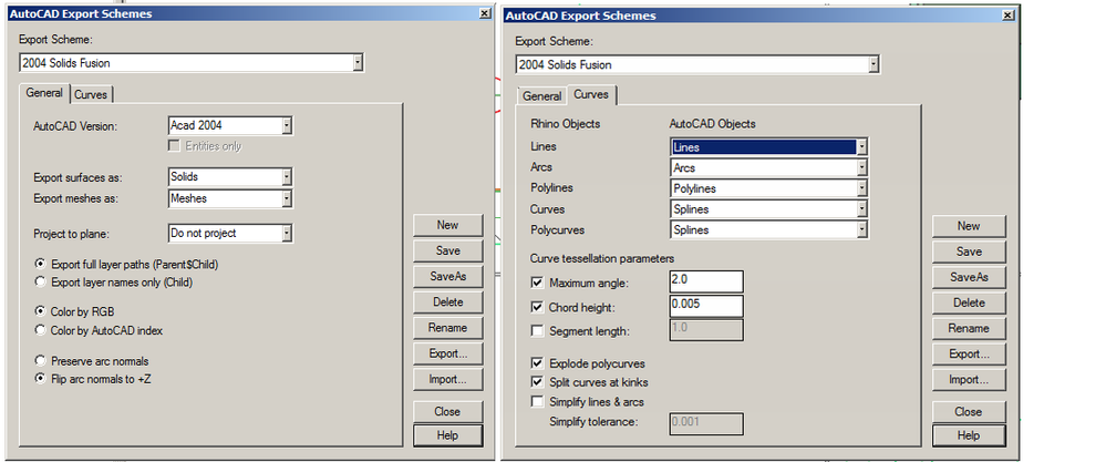
These setting will give you quite good exports from Rhino as a DXF. These setting seem to export splines quite well , Note the setting to explode polycurves and split curves at kinks. Can you share the original Rhino file? You'll need to ZIP it to upload to this forum.


Capture.PNG


Mark

Mark Hughes
Owner, Hughes Tooling
Did you find this post helpful? Feel free to Like this post.
Did your question get successfully answered? Then click on the ACCEPT SOLUTION button.

EESignature


Message 5 of 22

barry9UDQ6
Advocate
Advocate

I am going to try these settings for myself!


I have had problems in the past with ticking the maximum angle box, it caused my gentle curves to deviate quite badly from the original (and it was for cutfiles)

And whenever I have ticked the explode polycurves box my profiles have come through as open.

But I must have had another checkbox wrong somewhere.

0 Likes
Message 6 of 22

HughesTooling
Consultant
Consultant

Not sure the curve tessellation options do anything if you have Simplify unchecked. I found I needed explode polycurves checked because a mix of lines, arcs and splines in one curve caused problems, think it was multi spline curves that caused the most problems.


Mark

Mark Hughes
Owner, Hughes Tooling
Did you find this post helpful? Feel free to Like this post.
Did your question get successfully answered? Then click on the ACCEPT SOLUTION button.

EESignature


0 Likes
Message 7 of 22

g-andresen
Consultant
Consultant

Hi,

just something to illustrate


converted bezier.png


günther

0 Likes
Message 8 of 22

mcobb
Advocate
Advocate

This refinement to the export characteristics of Rhino looks really promising. I used your settings and brought in my image. The sketch information looks really clean and it appears to be a closed profile. However, I got the attached warning when I imported it and can't seem to generate an extrude from the result. Any thoughts are appreciated. Warning at import into Fusion.jpg


The file link is here: https://a360.co/3ev5LlH


I have also attached a simplified Rhino file. You will notice there are two closely spaced and parallel polylines that indicated the top and the bottom of the drafted surface. As per our discussion, I am working with the outer one and trying to create a tapered extruded void. Strangely, the polylines in the other rows above have functioned fine. Thank you for all your help. Invaluable.

Regards,

Mike
0 Likes
Message 9 of 22

mcobb
Advocate
Advocate

I'm not familiar with the convert-to-bezier process in Fusion but this does job a memory I have of first importing a dxf sketch and then converting it to something else before performing an extrude. Would you mind elaborating?

Regards,

Mike
0 Likes
Message 10 of 22

g-andresen
Consultant
Consultant

Hi,

Since a conversion to Beziér is not possible in Fusion, I did it in V-Carve pro.
The result can be found in the attached file above.
I just want to show that extruding, especially with taper, depends on a suitable profile.
How and with which application this is achieved is another story.


günther


0 Likes
Message 11 of 22

HughesTooling
Consultant
Consultant

The original curves don't look too bad but the offset ones are not good (these are the ones giving the error in Fusion). This is always a problem with offsetting splines especially in a polly curve. 

The exturde from the original curves look a lot better using the export setting I show above. It still doesn't work with a taper though. What do you need the taper for. Are you going to machine the part, if so does it actually need the taper?

HughesTooling_0-1619457860842.png


Mark Hughes
Owner, Hughes Tooling
Did you find this post helpful? Feel free to Like this post.
Did your question get successfully answered? Then click on the ACCEPT SOLUTION button.

EESignature


Message 12 of 22

jodom4
Community Manager
Community Manager

mcobb, are you still using that spreadsheet to make your dihedral angles, Mike? 😉


Jonathan Odom
Community Manager + Content Creator
Oregon, USA

Become an Autodesk Fusion Insider


Message 13 of 22

mcobb
Advocate
Advocate

I could geekily talk your ear off about that one. 🙂 ... but no, I am not using a spreadsheet for dihedral angles these days. 🙂


Regards,

Mike
0 Likes
Message 14 of 22

g-andresen
Consultant
Consultant

Hi,

I would just like to point out that the extrusion including the desired taper in the file attached above works.


günther

0 Likes
Message 15 of 22

mcobb
Advocate
Advocate

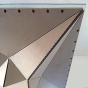
The mill produced will be used to cast a polyurethane rubber mold for some concrete work. See attached images of a sample prototype.


Yes, the offset profile is problematic for extrudes. I'm not planning on using that for any extrude operations. Instead, this inner line will be the path for a trace command during manufacturing. I am using a tapered bit to perform the milling around the perimeter of all the pockets. Right now, I am simply trying to define the model and this one extrude command is being problematic.


Looks like you were able to accomplish an extrude command with that problematic polyline. That is great! I wasn't able to accomplish even that. I wonder what you did differently than me? Thank you for all the help thus far.IMG_8544.JPGIMG_8556.JPEGIMG_8557.JPGIMG_8546.JPG

Regards,

Mike
0 Likes
Message 16 of 22

mcobb
Advocate
Advocate

!?!? I'm sorry, forgive my ignorance, which file are you referring to? Something you posted or a file that I posted?

Regards,

Mike
0 Likes
Message 17 of 22

g-andresen
Consultant
Consultant

Hi,


@mcobb wrote:

!?!? I'm sorry, forgive my ignorance, which file are you referring to? Something you posted or a file that I posted?


#2 >  „Part_NEW“     Tested < 6.3deg


günther

0 Likes
Message 18 of 22

mcobb
Advocate
Advocate

I see. Thank you. The taper is actually negative 4.36. I should have been clearer. For some reason he the taper reduces the width of the channel, this still does not work. Thank you for trying. So close. 😞

Regards,

Mike
0 Likes
Message 19 of 22

g-andresen
Consultant
Consultant

Hi,


@mcobb wrote:

I see. Thank you. The taper is actually negative 4.36. I should have been clearer. For some reason he the taper reduces the width of the channel, this still does not work. Thank you for trying. So close. 😞


Then position the sketch so that you can use a positive angle.


günther


ß

0 Likes
Message 20 of 22

HughesTooling
Consultant
Consultant

Looking at what you're doing you don't need to model the tapered extrude. If you use 2d contoured and setup a cutter with the correct angle the offset for the taper will be calculated for each depth. You could even use a parallel cutter, I seem to remember 2d pocket and contour have options for taper pocket if you use multiple depths.


Mark

Mark Hughes
Owner, Hughes Tooling
Did you find this post helpful? Feel free to Like this post.
Did your question get successfully answered? Then click on the ACCEPT SOLUTION button.

EESignature