Parametric construciton plane spescifying center point and orientation of plane

Parametric construciton plane spescifying center point and orientation of plane

rtorsvik5J67N
Explorer Explorer
2,993 Views
7 Replies
Message 1 of 8

Parametric construciton plane spescifying center point and orientation of plane

rtorsvik5J67N
Explorer
Explorer

Dear fusioners,


How can I make a construction plane where I can specify its origin and the orientation of the plane?


I want to use this plane as a base for creating a bracket for a stereo camera, and I want to be able to specify the translation and rotation of the plane so that I can easily plot this into a translation and rotation matrix. This is important because I want to stitch together point clouds from multiple cameras, and need to give them an exact position and orientation relative to the origin of my model.


I am trying to accomplish something like on the photo below, but this is only made "by hand" using the move command, and I am not certain about the angles.

Autodesk Fusion 360.jpg

0 Likes
Accepted solutions (2)
2,994 Views
7 Replies
Replies (7)
Message 2 of 8

chrisplyler
Mentor
Mentor
Accepted solution


Well, firstly, you need to understand that a Plane does not have a "center point." Planes are limitless, and as such, there are no two edges to measure a center between. The orange square is merely representative and is only to give you a visual clue about where the Plane is. The actual Plane, however, is not limited to that orange square.


There are many ways to make planes.


If you want to define and angle and distance from the Origin, for example, I sometimes sketch a construction line on an existing plane, and construct a new plane-on-a-path on that construction line. Like this:

planes01.JPG

Then you can control the position/angle of that plane by changing the sketch values (the could be parameters if you like). And if you want stuff sketched on that plane to always relate to a "center point" then when you first start sketching on it, Project in the endpoint of that construction line, and start building the rest of the sketch relative to that projected point as if it were an "origin" of sorts.


If you want the sketch for a new component to always be relative to an existing component, then create an offset-Plane right on the surface of that existing component (zero offset value), or a plane-at-angle right on an edge of that existing component, or whatever (to get the relative orientation you want). Again, when you start the new sketch, the first thing you should do is project in at least one useful point (perhaps the center of your existing hole, in your case) from the existing component geometry, and build the new sketch relative to that point.


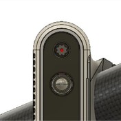
Sometimes it is necessary to use an intermediate Plane, and a sketch, on which to base the actual Plane you desire. For example, in my picture above, the sketch, and thus the new plane, was built relative to one of the Origin planes. What if I had wanted the new Plane angled somewhere BETWEEN the X and Y origin planes? I might have had to do something like this:

planes02.JPG

Message 3 of 8

lichtzeichenanlage
Advisor
Advisor
0 Likes
Message 4 of 8

MichaelT_123
Advisor
Advisor

Hi Mr. Chrisplyrer and IRobot rtorsvic5J67N,


As Mr. Chrisplyrer pointed out Planes are unlimited 2D points stretches, representing United Union Of Floating Points and obeying the unbreakable ( so far) law ALL POINT ARE EQUAL

However, every union (to my knowledge) has its own committee, which in this case is Coordinate System of Keeping  Points in Order. Naturally, the Committee on its own terms has the leader and it is always ZERO.  In F360, Planes together with their unelected Committee are called ConstructionPlanes

Most mortals ( unless they are crazy mathematicians or other non-technical creatures ) communicate with Planes only in an intermediary way by engaging plane's Committee's and always asking ZERO for the contribution (although same time indirectly with a help of brokers). You can join brokers organization, allowing better access to Planes but only in a nirvana of Direct Modeling Paradigme.

The ‘planes’ you see on pictures laboured by Mr. Chrisplyrer are just representation of  ConstructionPlanes. As viable committee’s of respecting Planes, they have their own secretaries.

In the case of F360, they are geometry which has received a petition, gives access to administration and enforcement members like:

  • origin               - Honorable Member ZERO
  • normal             - official Point of View of the Committee
  • uDirection       - uFaction
  • vDirection       - vFaction
  • evaluator         - gives you access to the surface of a lower chamber

So, it seems that everything is in place to help you with your goal. It is just a matter to devise a cohesive policy and ask ZERO for its acceptance. WARNING: Any division by later will have unpredictable consequences!


Regards

MichaelT


MichaelT
Message 5 of 8

rtorsvik
Explorer
Explorer
Accepted solution

Thank you very much!


The latest picture will help me accomplish what I'm trying to do. Then I should probably do something like this, where I can specify x-y-z coordinates of a point, and also the angles of the plane.

Reply to Message - Autodesk Community - Google Chrome.jpg


And yes, planes may not have a center point. However, when you make a construction plane, it will have an origin that I can use as a reference. Alternatively, I can project the end point of the construction line as you suggest.


Kind regards

Rein

0 Likes
Message 6 of 8

rtorsvik5J67N
Explorer
Explorer

And thank you for this entertainment, supreme court justice MichaelT


Kind regards

Auto-generated entity rtorsvik5J67N

0 Likes
Message 7 of 8

rtorsvik5J67N
Explorer
Explorer

I am sorry, but this rendered an "Access Denied" page where it says I do not have sufficient privileges.

0 Likes
Message 8 of 8

chrisplyler
Mentor
Mentor

@rtorsvik wrote:


And yes, planes may not have a center point. However, when you make a construction plane, it will have an origin that I can use as a reference. Alternatively, I can project the end point of the construction line as you suggest.


I'm glad to help. Here is something to keep in mind:


SOME plane construction types will precisely place that "plane origin." For example, a Plane-on-a-Path puts it on the line you selected as a path. And since that plane is perpendicular to that line/path, that point is definitive.


Let's look at a different type though. A Plane-at-an-Angle also needs a line or edge to be selected, but the "plane origin" will just be somewhere along that line/edge, presumably just wherever you clicked. It won't be in a precise, definitive location.


That's why I suggest developing the habit of just Projecting in at least one useful point (if not more, depending on what you might want to do with the sketch) that IS definitive.


And let me elaborate on the content of those parenthesis in the previous sentence. If you're going to build a bracket where you showed that plane in your first picture, you might not only want it to maintain position on the back of that existing geometry, but also rotation. So, you might want to Project in the center point of that hole that you have the axis through, and you MIGHT want to also project in one of the straight edges. So you could LOCATE your bracket relative to the hole, and you could constrain a bit of it to be parallel to that edge. In this way, the desired relationship would be maintained regardless of how you reposition that existing item.