Hole feature and modeled thread

Hole feature and modeled thread

Remy18
Enthusiast Enthusiast
3,478 Views
9 Replies
Message 1 of 10

Hole feature and modeled thread

Remy18
Enthusiast
Enthusiast

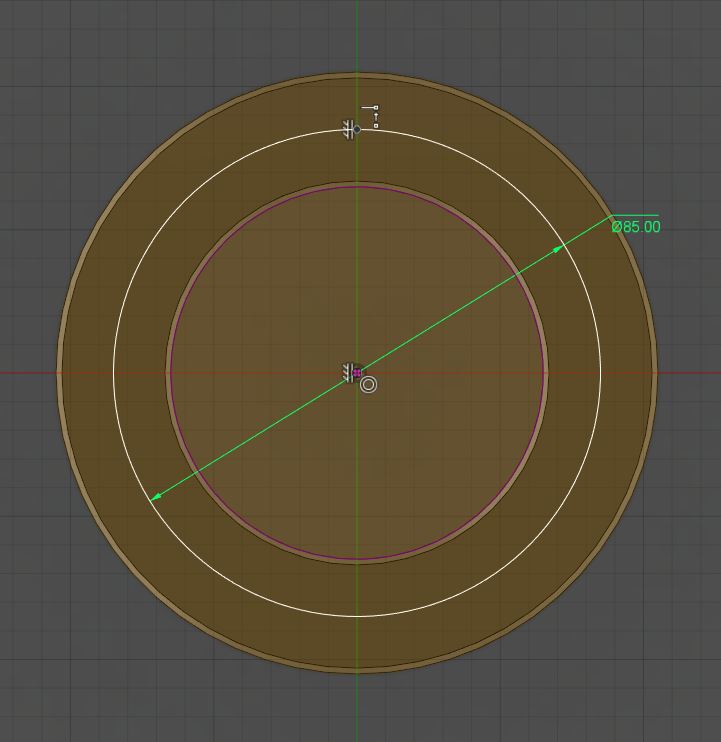
Like the screenshot shows, I did create a hole feature with a sketchpoint reference and made a circular pattern together with a chamfer and thread feature. When the pitch circle diameter has been changed to 90 it losses its references and shows no selection ("Circular pattern 1 hole PDC90 lost ref"). The hole pattern stays at the PDC85. If the "From Sketch (multiple holes)" option is used it seems to work and remembered it's single sketch point reference. Do i use the wrong workflow ?


Also it would be nice to see some small enhancement in the hole feature like chamfer options at all edges of a Hole type. Thereby an option to create standard center holes with this feature, which would be common at turning products.


A small improvement for the thread feature would be the appearance of the thread's lead in and -out if a chamfer to a hole is applied.("Thread feature chamfer")


3,479 Views
9 Replies
Replies (9)
Message 2 of 10

TrippyLighting
Consultant
Consultant

The reason the holes circle dimater does not change when you increas the size of the sketched circle is one of these two:


1. The sketch point you made is not coincident with the circle.

2. The hole is not coincidet with that sketch point.


EESignature

0 Likes
Message 3 of 10

Remy18
Enthusiast
Enthusiast

The sketch point is coincident with the pitch circle at the sketch using constraints.("Coincident sketch point") 


Like I mentioned before, the placement selected at the hole feature seems to make the difference. If "at point" is selected, it snaps at the sketch point but no reference is shown and made. So it's lost if the PCD is changed inside the sketch. If the placement "from sketch" is selected it stays referred to the sketch point. Did I overlook an option to make the hole coincident with the sketch point ?


What strikes is a modify to the hole feature. It isn't possible to change the placement selection after the feature is applied. The way to change the placement afterwards, is re-applying the hole feature. The referred features to the hole feature will be lost then...

0 Likes
Message 4 of 10

O.Tan
Advisor
Advisor

hole wizard.png

You mean something like this? 😉

You're not going to get this in Fusion anytime soon I think, there's just too many backlog on requested features and more new features they plan to add which makes me wonder when such useful productivity features like what you mentioned or the photo I pasted above will appear in Fusion. Also for 1 year already, they haven't solved the blind hole thread depth bug (try create a hole of depth 12 with diameter 3 and create thread of M20, open the hole feature again and you'll see that the depth is no longer 12).


Though my guess is when they finally update the hole stuffs, hopefully they'll also add the much needed Hole Callouts in Drawings, makes no sense that I have to refer back to my model to know what size is the hole and then if I changed it, have to manually update it back. When when when, oh and not to mention, still waiting for coordinate/ordinate dimensions in drawings. 


I'm still waiting for the season where they'll focus on exisiting mainstream CAD features to be implemented in Fusion rather then adding new ground breaking features when the "foundation" or so to speak isn't done.

And yeah, I'm nagging here as I'm frustrated with the Fusion experience as of late.


---


Back to your question, any particular reason why you choose to work with modelled thread? As you'll have issues like getting the center of the hole and etc. Best way to implement modelled thread is at the very end of your modelling stage, when you're going to submit for render or 3D printing.


Omar Tan
Malaysia
Mac Pro (Late 2013) | 3.7 GHz Quad-Core Intel Xeon E5 | 12GB 1.8 GHz DDR3 ECC | Dual 2GB AMD FirePro D300
MacBook Pro 15" (Late 2016) | 2.6 GHz Quad-Core Intel Core i7 | 16GB 2.1 GHz LPDDR3 | 4GB AMD RadeonPro 460
macOS Sierra, Windows 10

Message 5 of 10

TrippyLighting
Consultant
Consultant

It seems to me the method for placing holes in particular modifying the placement after the hole is created is bugy ot lets say not fully thought trough.


When I place the hole initially by selecting the sketch point it creates a constraint that is not visible in the viewport. the only indicaion is tht "Face/Point" ches to "1 selected". But it dies that also if there is no coincident constraint created with the sketch point.


If you do decide later on to edit the hole location because pehaps you don't want it constrained with the skech point anymore the "1 selected" can be deleted but then I fait to be able to select any other point ot the sketch surface for hole placement.


Either I am also overlooking something or there is simply someting left to be desired.


EESignature

0 Likes
Message 6 of 10

TrippyLighting
Consultant
Consultant

@O.Tan


I agree that we get a lot of new-toy-bling while real productivity topics such as a more powerfull hole generation tool are left in the dust.


EESignature

Message 7 of 10

promm
Alumni
Alumni

@Remy18


Thank you for the feedback on your frustrations with the hole and thread features.  Let me start by saying that we do have plans to improve the hole and thread workflow, many of your suggestions are valid.  But I don't want to stop there, working with our CAM team we envision a hole/thread feature that directly connects to CAM.  Let me explain further, when you create a hole with say 1/4" threads you actually drill a smaller hole first and then tap.  Along with this there are tolerances to consider, when you have -.00" and +.06" the part is machined at .03" with a +/- of .03".  Many of these things happen behind the scenes if you do not manufacture your own parts and the people that do often have to change the model for manufacturing.  Our proposed solution would include all of this.  I do not have a timeframe for the solution yet due to some dependencies that need to get done first.  


I also want to address a comment that was said later in the thread "I'm still waiting for the season where they'll focus on existing mainstream CAD features to be implemented in Fusion rather then adding new ground breaking features when the "foundation" or so to speak isn't done".   You are not the only person that has this perception and I do understand where you are coming from.  In the last year we have added things like CAM and Simulation.  It would appear that we have taken people from our "foundation" to develop these features.  Let me assure you this is not the case; the new functionality came from specialized resources in these fields.  The majority of our team is focused on the "foundation" and have been developing additional functionality along with architecture to support an integrated desgn tools set.

0 Likes
Message 8 of 10

Remy18
Enthusiast
Enthusiast

For now it is ok for me to use a workaround. But I still can imagine if you're not aware of this bug your Assembly would also be incorrect cause of joints used at holes to specifiy the right references.

0 Likes
Message 9 of 10

TMC.Engineering
Collaborator
Collaborator

Oh man, I wish I could put +100 on this. I missed one annotation that needed to be updated for a threaded hole on a drawing.  


End result:

  1. money paid to my machinist to rework part (luckily hole got bigger, don't have to remake)
  2. 1 week extra time wasted due to rework
  3. might mis delievery to my customer

Don't get me wrong I really like fusion, but it is vary frustrating when it costs money.  I need to get better at catching these catching these changes.

Timm

Engineer, Maker
System: Aorus X3 Plus V3, Windows 10
Plymouth Michigan, USA
Owner TMC Engineering
0 Likes
Message 10 of 10

TrippyLighting
Consultant
Consultant

What bug are you referencing?


EESignature

0 Likes