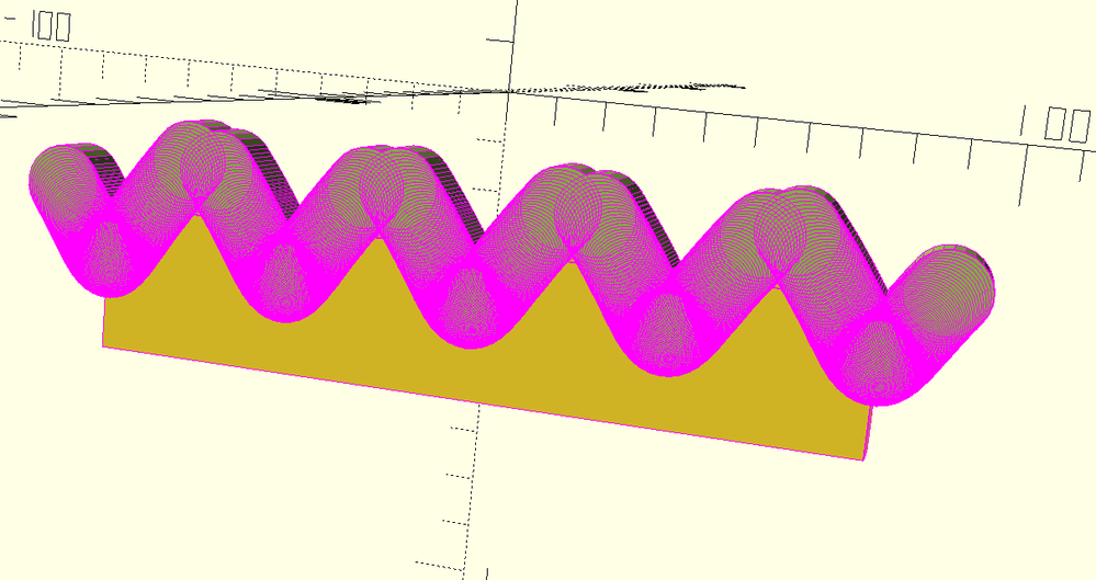
Cutting out or creating the shape of a rack through a moving roller pinion

Cutting out or creating the shape of a rack through a moving roller pinion

fusion1BXBB2
Contributor Contributor
8,395 Views
59 Replies
Message 1 of 60

Cutting out or creating the shape of a rack through a moving roller pinion

fusion1BXBB2
Contributor
Contributor

Hello guys,

currently i am working on a project where i want to use the roller pinion and rack system (e.g. Nexen rpg) instead of a standard rack and pinion. Unfortunately, to create the correct rack i would need a script or so to do the math. I am not able to do that by myself. I have found 2-3 people who seem to have created such scripts. One can be found through the thingverse page (https://www.thingiverse.com/thing:1013816), but i get a error message when loading the script.


So, my question is: Is it possible to do something similar in Fusion 360, e.g. to cut out a shape of a body through a moving object? More specific: I want to move the pinion along a path and automatically create the correct shape of the rack.

In case thats not possible, are there any alternatives for someone without any coding knowledge?


Ps: I am in contact with someone from US who can create the shape of the rack for me with his script, but due to the fact that i have to play around with the pinion size, i would need to ask him many times to create the rack for me. He is in US and i am in Europe, so i believe we will exchange a mail once a day, but i am a bit in hurry. (i am still very thankful that in case i will not get it done by myself i still have someone who can help me out, but of course i dont want to use his time)


Thanks in advance!

Best regards,

Denis


roller_rack_picture.png


Accepted solutions (1)
8,396 Views
59 Replies
Replies (59)
Message 21 of 60

MRWakefield
Advisor
Advisor

@fusion1BXBB2 wrote:

It took me about 15 minutes, but now i get it. Very good explained. Thank you!

I think its fine if not all rollers are full in contact, as long as the pinion runs perfectly and has no backlash.

About the pdf:  I mean this one: Precision-Motion-control-21282.pdf  , from your message nr. 15 .

You have spent almost the whole day helping me. I would say that my problem is solved. Also i think that i am able to create my own rack for different size pinions (with the help of your drawing and the formulas), but on today i noticed that my Fusion 360 skills are really low. I have to learn to use all the drawing functions, learn to use formulas and so on. Now i need to go to sleep, but i can continue my project.

Thanks!


That's great, I'm glad I was able to explain it so it was understandable! The message with the PDF wasn't from me, it was from @Warmingup1953 .


Anyway, good luck with it all, let us know how it goes.

If this answers your question please mark the thread as solved as it can help others find solutions in the future.
Marcus Wakefield


____________________________________________________________________________________
I've created a Windows application (and now Mac as well) for creating custom thread files for Fusion. You can find out about it here. Hope you find it useful.
If you need to know how to offset threads for 3D printing then I've created a guide here which you might find useful.
If you would like to send me a tip for any help I've provided or for any of my software applications you've found useful, you can do this via my Ko-Fi page here.
____________________________________________________________________________________

0 Likes
Message 22 of 60

fusion1BXBB2
Contributor
Contributor

Oh okay, sorry i didnt know it was posted by someone else.


I am currently ordering everything i need, but the first tests i will do with cnc. That way i can check also how precise my cnc router actually is. If i manage to get the bearings until tomorrow then i should know more this weekend already.

I will inform you how it went.

I wish you all a nice weekend:)

0 Likes
Message 23 of 60

MRWakefield
Advisor
Advisor

After my last post I started working on an app for calculating the points along a cycloid. I finished it off this morning and have attached it as I think you might find it useful (although it is good experience and interesting to sketch it manually). You'll need to use the 'ImportSplineCSV' script to create the spline from the points generated. Note that this script uses 'cm' units when importing the coordinates! This only generates the cycloid corresponding to your PCD (Pitch Circle Diameter) so you'll need to offset, mirror and add the root radius etc. yourself. It would also be a good idea to flatten off or radius the sharp points of the teeth otherwise they're likely to break off.


MRWakefield_1-1709291845043.png


MRWakefield_2-1709291953969.png


MRWakefield_3-1709292201450.png


Hope you find this useful. If you have any questions just let me know.


If this answers your question please mark the thread as solved as it can help others find solutions in the future.
Marcus Wakefield


____________________________________________________________________________________
I've created a Windows application (and now Mac as well) for creating custom thread files for Fusion. You can find out about it here. Hope you find it useful.
If you need to know how to offset threads for 3D printing then I've created a guide here which you might find useful.
If you would like to send me a tip for any help I've provided or for any of my software applications you've found useful, you can do this via my Ko-Fi page here.
____________________________________________________________________________________

Message 24 of 60

MRWakefield
Advisor
Advisor

@fusion1BXBB2 wrote:

Oh okay, sorry i didnt know it was posted by someone else.


I am currently ordering everything i need, but the first tests i will do with cnc. That way i can check also how precise my cnc router actually is. If i manage to get the bearings until tomorrow then i should know more this weekend already.

I will inform you how it went.

I wish you all a nice weekend:)


No problem.


Great, it'll be interesting to find out how well it all fits together.


Have a great weekend yourself.

If this answers your question please mark the thread as solved as it can help others find solutions in the future.
Marcus Wakefield


____________________________________________________________________________________
I've created a Windows application (and now Mac as well) for creating custom thread files for Fusion. You can find out about it here. Hope you find it useful.
If you need to know how to offset threads for 3D printing then I've created a guide here which you might find useful.
If you would like to send me a tip for any help I've provided or for any of my software applications you've found useful, you can do this via my Ko-Fi page here.
____________________________________________________________________________________

0 Likes
Message 25 of 60

fusion1BXBB2
Contributor
Contributor

Amazing, that will be very helpful.

On the evening i will try out the script. Thank you.

I didnt manage to get the bearings for this weekend, but on tuesday they should arrive.

I think i will machine the parts until Tuesday and then assembly it and test it out.

0 Likes
Message 26 of 60

HughesTooling
Consultant
Consultant

@MRWakefield wrote:

No problem, I like trying to solve things like this. It might not be perfect and I'm sure someone else could come up with a more elegant or simpler solution but I hope it helps.


@MRWakefield Don't suppose you know how to calculate the undercut need if you have an involute gear with less than about 20 teeth running with a large gear or on a rack? There are lots of scripts around that create an involute gear (one supplied with Fusion) but none of them produce the correct form for gears with a few teeth.

Here's an example of a gear running on a rack. I've included the f3d file with a motion link.

HughesTooling_0-1709302328456.png

I've created scripts for other programs that create the involute but can't get my head around the path the point of the rack creates.


Edit Updated attached file to an f3d.


Mark Hughes
Owner, Hughes Tooling
Did you find this post helpful? Feel free to Like this post.
Did your question get successfully answered? Then click on the ACCEPT SOLUTION button.

EESignature


0 Likes
Message 27 of 60

MRWakefield
Advisor
Advisor

@HughesTooling wrote:

@MRWakefield wrote:

No problem, I like trying to solve things like this. It might not be perfect and I'm sure someone else could come up with a more elegant or simpler solution but I hope it helps.


@MRWakefield Don't suppose you know how to calculate the undercut need if you have an involute gear with less than about 20 teeth running with a large gear or on a rack? There are lots of scripts around that create an involute gear (one supplied with Fusion) but none of them produce the correct form for gears with a few teeth.

Here's an example of a gear running on a rack. I've included the f3d file with a motion link.

HughesTooling_0-1709302328456.png

I've created scripts for other programs that create the involute but can't get my head around the path the point of the rack creates.


Unfortunately not, my poor little brain has its limits 😂. Like you I have written software to create involutes (and even complete gears). However these are very basic with no undercutting or profile shifting capability. There's an excellent and very informative PDF that QTC Gears have available for download here which is very comprehensive (124 pages!) and includes info on undercutting and profile shifting.


There's also a profile generator here that looks on the face of it to support undercutting.


EDIT:

Here's a better calculator that looks suspiciously similar to the earlier link I posted but as well as undercutting this one also supports profile shifting 😀


Hope this helps.

If this answers your question please mark the thread as solved as it can help others find solutions in the future.
Marcus Wakefield


____________________________________________________________________________________
I've created a Windows application (and now Mac as well) for creating custom thread files for Fusion. You can find out about it here. Hope you find it useful.
If you need to know how to offset threads for 3D printing then I've created a guide here which you might find useful.
If you would like to send me a tip for any help I've provided or for any of my software applications you've found useful, you can do this via my Ko-Fi page here.
____________________________________________________________________________________

Message 28 of 60

MRWakefield
Advisor
Advisor

Actually, I might be thinking this is harder than it really is. I'll have a bit of a think...

If this answers your question please mark the thread as solved as it can help others find solutions in the future.
Marcus Wakefield


____________________________________________________________________________________
I've created a Windows application (and now Mac as well) for creating custom thread files for Fusion. You can find out about it here. Hope you find it useful.
If you need to know how to offset threads for 3D printing then I've created a guide here which you might find useful.
If you would like to send me a tip for any help I've provided or for any of my software applications you've found useful, you can do this via my Ko-Fi page here.
____________________________________________________________________________________

0 Likes
Message 29 of 60

MichaelT_123
Advisor
Advisor

Hi Mr HughesTooling,


It is not difficult to explain … and find a no-good solution.

A tooth of gear/pinion has two main parameters: width and height.

 When both gear and pion teeth intermingle with each other in a pairing setup (called meshing), they mutually interchange between themselves 'width for height' and 'height for width' of their respective teeth.

An undercut occurs with insufficient 'width' on the pinion side. This suggests the potential solutions:

All the above will be trade-offs, so it is a no-good solution. The geometry is merciless!


CycloidGear_Planet_mono.png


Attached files:

CycloidGear_Planet_mono.png    4K_mono    (0.6MB)  https://a360.co/3wJykIC 

CycloidGear_Planet_mono.mp4   4K_mono    (11MB)  https://a360.co/49AiWwP 

CycloidGear_Planet_arcd.mp4     4K_stereo   (24MB)  https://a360.co/49A6uxc 


To be viewed on 4K media devices (monitors, UHD TVs, projectors...) of reasonable performance. For the best experience, use stand-alone media applications (WMP, VLC) and the native resolution 3840x2160 - full screen. The '_arcd' files require an anaglyph red/cyan glasses, while '_al' is for active shutter glasses 3D hardware (~30 deg viewing angle is recommended). Download the files over a network, where the cost of doing so is not a concern. The files are to be used for private, non-commercial purposes only.


Regards

MichaelT

MichaelT
0 Likes
Message 30 of 60

fusion1BXBB2
Contributor
Contributor

Hello guys,

i am not sure if the posts after me can be ignored or if it means that the drawings with the changable parameters are not correct?

I have downloaded the NEXEN RPS10 rack and pinion CAD file. The PCD is 30mm, roller diameter 4mm, quantity of rollers: 8.

I measured between center of one roller to another and the measurements are different than from what i get from the drawing made by MRWakefield. 

I am think of just trying it out with the drawing of the rack from Nexen in case the drawing where i change the parameters is not correct.

overlayed over the NEXEN RPS10overlayed over the NEXEN RPS10original NEXEN RPS10original NEXEN RPS10

0 Likes
Message 31 of 60

MRWakefield
Advisor
Advisor

Can you post the Nexen pinion cad file you've got and a link to the Nexen page so I can check it out.


EDIT:

BTW, the pinion shown in your post has 10 rollers rather than the 8 in your description.


EDIT #2:

Actually, would you mind attaching the rack model as well as any other ducumentation you have. I don't really want to set up an account with Nexen just to download some models and docs. Thanks.

If this answers your question please mark the thread as solved as it can help others find solutions in the future.
Marcus Wakefield


____________________________________________________________________________________
I've created a Windows application (and now Mac as well) for creating custom thread files for Fusion. You can find out about it here. Hope you find it useful.
If you need to know how to offset threads for 3D printing then I've created a guide here which you might find useful.
If you would like to send me a tip for any help I've provided or for any of my software applications you've found useful, you can do this via my Ko-Fi page here.
____________________________________________________________________________________

Message 32 of 60

fusion1BXBB2
Contributor
Contributor

Oh ****, you are right. I feel stupid now.

I changed it to 10 rollers, but the rack pitch is still different, but now the distance between the rollers is correct.

Link to nexen rps10 pinion: https://www.nexengroup.com/966484-rps10p-b012-00mmp2

Link to nexen rps10 rack:     https://www.nexengroup.com/966975-rps10r-b0250p2r

*EDIT*:    I have attached the original pinion and rack as attachment.

Here i overlayed the rack over the original nexen rack drawing (green).

CPA1010B-1A v1___3.png


0 Likes
Message 33 of 60

MRWakefield
Advisor
Advisor

I'd say it looks like Nexen are being a bit protective of their design (understandably). The pinion data on the Nexen page doesn't agree with their model! They state a PCD of 31.8mm (which agrees with the 'Distance Per Revolution' figure of 100mm, 100mm/Pi = 31.831mm). However their pinion model has a 30mm PCD (which would give a distance per rev of 94.248mm). I believe they've also modified the model of the rack to suit the 'doctored' pinion model. The pitch is correct but the actual form has been modified so instead of being a cycloid they've made it a simple arc such that when meshed with their pinion model it 'looks right'.


If you have an actual pinion in your hand and measure the outside distance across diametrically opposite pins you should get a distance of 35.831mm (31.831+4). That's assuming a pin diameter of 4mm.


It's not unusual for manufacturers to protect their intellectual property by providing doctored models etc. As long as it is representative and satisfies the requirements when inserted into an assembly.


If you plug the correct PCD etc. into my model you should get the correct profile***.


Hopefully this makes sense and don't forget to let us know how you get on.


***EDIT:

If you're using my cycloid generator app don't forget you'll need to generate a new cycloid from the correct PCD!


If this answers your question please mark the thread as solved as it can help others find solutions in the future.
Marcus Wakefield


____________________________________________________________________________________
I've created a Windows application (and now Mac as well) for creating custom thread files for Fusion. You can find out about it here. Hope you find it useful.
If you need to know how to offset threads for 3D printing then I've created a guide here which you might find useful.
If you would like to send me a tip for any help I've provided or for any of my software applications you've found useful, you can do this via my Ko-Fi page here.
____________________________________________________________________________________

0 Likes
Message 34 of 60

fusion1BXBB2
Contributor
Contributor

You are doing for me what i should actually do. (check the details as you did)

I changed the PCD to 31.831 mm and now the rack pitch is exactly 10.00 mm. All makes sense now. Thank you for that.

Actually i was thinking also that maybe they dont provide accurate drawings to protect the design. Good to know that its actually like that. 

Just one question: Do you believe the Nexen Rack has actually the same form as what i get from your drawing where i change the parameters, but they just changed the drawing? As you noticed, the cutout for the roller in the Nexen rack has more space and generally has a different form.

I havent used your fusiuon 360 app yet, because changing the parameters of your drawing is so quick and easy, but i will for sure test it out.


Of course i want to share what i build and let especially you know if its working, but i didnt order the harmonic drive yet, so i cannot machine the bearing seats in the pinion very accurate. I have a couple of options. Some used and some new harmonic drives. For the new ones i would need to wait at least a couple of days and the used one i could have in 2 days if i order today, but i am just thinking if it makes sense to buy a used harmonic drive for the 4th axis to do very precise work. If its used, it might be not anymore in best condition and the price is about the same as for a new china harmonic drive. (with good reputation)


But, i have some news or at least i can show i take that small project seriously :D:

I did some tests yesterday. I found some bearing roller shafts in 4mm size and i had exactly 9 rollers, so i thought i will machine a pinion and just put the rollers between the pinion plates without any bearings, just for fun, and also i machined a rack for the Pinion.

Just some additional information: I didnt have much time yesterday, so i just mounted the 6mm aluminium sheet plate on my router table with 2-sided tape. It holds well when the surface is big, but not in case of 30mm parts like the pinion, so the quality of the outside surface of the pinion is bad. But, also i first used a broken collet (i didnt know its broken) from which i had 0.11 mm runout on the 3mm cutter i used. The i found another but rusty 4mm collet, cleaned it well and got 0.005 runout (i was very shocked that the rusty collet that i could clean only on the outside gave me such good runout). With the perfect runout i than machined the rack, but also the rack was cutted from the same sheet that was mounted with the 2 sided tape and even the surface is very good, its not as i know it. My router is pretty stiff for a 4x8 size router and makes almost a polished finish when the material is well fixed.

The 4mm holes i did with "bore-milling", unfortunately with the3mm end mill with 0.11mm runout, but the hole are pretty good for the roller, but they are not all in perfect distance to each other. Error of 

The PCD of the pinion i machined is originally 24.00 mm.

Here the measurements from one roller to the opposite roller:

1.  27.97 mm

2. 27.96 mm

3. 27.94 mm

4. 27.93 mm 

So, about 0.05 mm error. I think its not bad with a 0.11 run out and bore milling of every roller and all by cnc with 2-sided tape fixture.

The Rack seams to be almost perfect. When i lie in a 4mm end mill shaft into the teeth-cutout, you cannot move it. It feels really good.

Now when i move the Pinion over the rack, you cannot feel any backlash, but keep in mind the rollers dont roll, because there are no bearings. It also doesnt feel smoth, but no wonder without bearings and also the 0,05 mm error shouldnt be there.


After this test i am pretty sure i can build that system and it will work well, i just need a harmonic drive and do it as i previously described:

1. Mount pinion stock material on harmonic drive. (like on a vertical lathe)

2. Pre-drill 1 hole

3. rotate stock by 54.802 deg. (for PCD = 24 mm)

4. Pre-drill next hole 

5. when all holes a pre-drilled then finish all holes with a reamber or boring head

Pinion is done


When it comes to the Rack i have a couple of options.

1. Option: I can do it as i did yesterday - just use CNC for machining the rack (lowest accuray i would say)

2. Option: I create a contuor for one cutout (for one roller) and after one cut, i will move the stock rack material exactly by the specific distance and then cut the next cut out. (in this case i have to build a fixure and the stock material has to have one flat surface that i can butt against the fixture - i hope you understand what i mean)

3. Pre-cutting the rack with CNC, then use a shaped/dressed grinding wheel and do it same like for Option 2. (this should be the most advanced and accurate/precise option, but that would be a option in case i would like to start a small business with that roller rack&pinion system and if the racks has to be hardened.)


Now here some pictures: 

photo_2024-03-04_15-23-52 (3).jpgphoto_2024-03-04_15-23-52 (2).jpgphoto_2024-03-04_15-23-52.jpgphoto_2024-03-04_15-23-51 (4).jpgphoto_2024-03-04_15-23-51 (3).jpgphoto_2024-03-04_15-23-51 (2).jpgphoto_2024-03-04_15-23-51.jpg


0 Likes
Message 35 of 60

MRWakefield
Advisor
Advisor

It certainly looks like you're making good progress 😀


@fusion1BXBB2 wrote:

You are doing for me what i should actually do. (check the details as you did)

I changed the PCD to 31.831 mm and now the rack pitch is exactly 10.00 mm. All makes sense now. Thank you for that.

Actually i was thinking also that maybe they dont provide accurate drawings to protect the design. Good to know that its actually like that. 

Just one question: Do you believe the Nexen Rack has actually the same form as what i get from your drawing where i change the parameters, but they just changed the drawing? As you noticed, the cutout for the roller in the Nexen rack has more space and generally has a different form.

I havent used your fusiuon 360 app yet, because changing the parameters of your drawing is so quick and easy, but i will for sure test it out.

I'm confident that the profile of the Nexen rack will be the same as that generated by my model. There really isn't any other form that would work for this. It's all pretty basic geometry and there's only one correct profile. You could make it more accurate by adding more nodes but you might find it good enough as it is.


In case you hadn't thought of it you'll probably need to truncate the apex of the teeth so that they clear the central hub of the pinion. Another thing is that if you find your home-made rack binding at all you might want to incorporate a small amount of clearance between the roller and the tooth flank. Just add a few microns to the offset in the cycloid profile sketch. That will introduce some backlash though.


I wouldn't worry about using the app if the Fusion model I provided gives a good enough profile. Although it's easy to increase the number of points in the app it is more difficult to update a model that's used an imported curve than one actually generated inside Fusion. However, if you're creating a new design the app does make it a lot easier and more accurate.


I've actually just updated the app so I've attached the new version.


Good luck and keep us posted!

If this answers your question please mark the thread as solved as it can help others find solutions in the future.
Marcus Wakefield


____________________________________________________________________________________
I've created a Windows application (and now Mac as well) for creating custom thread files for Fusion. You can find out about it here. Hope you find it useful.
If you need to know how to offset threads for 3D printing then I've created a guide here which you might find useful.
If you would like to send me a tip for any help I've provided or for any of my software applications you've found useful, you can do this via my Ko-Fi page here.
____________________________________________________________________________________

0 Likes
Message 36 of 60

fusion1BXBB2
Contributor
Contributor

@MRWakefield wrote:

It certainly looks like you're making good progress 😀


I'm confident that the profile of the Nexen rack will be the same as that generated by my model. There really isn't any other form that would work for this. It's all pretty basic geometry and there's only one correct profile. You could make it more accurate by adding more nodes but you might find it good enough as it is.


Perfect! Thanks.:)


In case you hadn't thought of it you'll probably need to truncate the apex of the teeth so that they clear the central hub of the pinion. Another thing is that if you find your home-made rack binding at all you might want to incorporate a small amount of clearance between the roller and the tooth flank. Just add a few microns to the offset in the cycloid profile sketch. That will introduce some backlash though.


Good ideas. Actually i also thought that i might be a good idea to incorporate a small amount of clearence, but i thought that i will do that only at the bottom of the rack between the teeth where 4mm roller fits perfectly (as it can be seen on the picture with the end mill). I earlier wrote already that it feels good, but in sense of precision, if i can say so. The end mill "sits almost tightly". Maybe if i put some clearence there it will be enough.

Now about truncating the apex of the teeth: I just put some clearence there, so that the roller does not "lock in" at that spot.

I am trying to explain it as good as possible:). Hope you understand. 


I wouldn't worry about using the app if the Fusion model I provided gives a good enough profile. Although it's

easy to increase the number of points in the app it is more difficult to update a model that's used an imported curve than one actually generated inside Fusion. However, if you're creating a new design the app does make it a lot easier and more accurate.


I've actually just updated the app so I've attached the new version.


Good luck and keep us posted!


I just downloaded the new version of your app. I tried it with meter values and mm values, but in both cases i just get a very long line in fusion, i cant even scroll out to see the ends. I did it as you described ealrier. E.g. 24 diameter and 20 points. Then i hit Generate andsave it. In Fusion i go to utilities, Add-ins, Script and Add-ins, then i choose ImportSplineCSV and hit "RUN". I choose the script previously created with your app and then i just get a drawed line.

I have tried it now for a couple of times with different values and Fusion even crashed once. Maybe i am doing something wrong, but i believe all steps where correct. Do you have an idea?


And yes, i will keep you updated. I am still searching for a good harmonic drive. As soon as its ordered, i will order all other parts like bearings and rolles. When it comes to bearings i will order the cheapest and the more expensive bearings and see if there will be any difference. Just as an example: HK 0306 T MGK type bearing costs about 0,35 € , and a better, quality bearing in the same size costs almost 3€ per pcs.


Here a 2 interesting pictures: 

*I have put black marker und the rack running surface and checked where there is contact. You can see very well where there is no contact. It seems that this is happening when one roller is in the "locked position" in the lowest position of the rack between 2 teeth.

photo_2024-03-04_19-34-04 (2).jpgphoto_2024-03-04_19-34-04.jpg

0 Likes
Message 37 of 60

MRWakefield
Advisor
Advisor

If you take a look at message #23 you'll see I mention that the ImportSplineCSV script assumes cm as the unit so you need to enter 3.1831 into the diameter field.

MRWakefield_0-1709580172062.png


The reason you might be seeing a line is that you might be looking at it from the wrong direction 😉. If your environment is set to 'Z up' you'll need to look at it from the top view to see the curve. If you want it to be on the XZ plane you can just redefine the plane after importing the CSV (be aware though that it might flip direction). Let me know if you need any more help.


If this answers your question please mark the thread as solved as it can help others find solutions in the future.
Marcus Wakefield


____________________________________________________________________________________
I've created a Windows application (and now Mac as well) for creating custom thread files for Fusion. You can find out about it here. Hope you find it useful.
If you need to know how to offset threads for 3D printing then I've created a guide here which you might find useful.
If you would like to send me a tip for any help I've provided or for any of my software applications you've found useful, you can do this via my Ko-Fi page here.
____________________________________________________________________________________

0 Likes
Message 38 of 60

MRWakefield
Advisor
Advisor

Ok, so I've just added the ability to select the coordinate plane.


MRWakefield_1-1709581941017.png


Here's a screenshot showing the result of importing the curve on all three planes.

MRWakefield_0-1709581921118.png


Find latest version attached.


If this answers your question please mark the thread as solved as it can help others find solutions in the future.
Marcus Wakefield


____________________________________________________________________________________
I've created a Windows application (and now Mac as well) for creating custom thread files for Fusion. You can find out about it here. Hope you find it useful.
If you need to know how to offset threads for 3D printing then I've created a guide here which you might find useful.
If you would like to send me a tip for any help I've provided or for any of my software applications you've found useful, you can do this via my Ko-Fi page here.
____________________________________________________________________________________

0 Likes
Message 39 of 60

fusion1BXBB2
Contributor
Contributor

Thanks for your quick reply.

I noticed that you wrote in post 23 about the cm, (in my last post i wrote meter and mm, but it should be cm and mm), but what i also noticed is that i cannot put "." into the diameter field, but only ","  so e.g. 3,183 is possible, but not 3.183.

On your pictures you can set a point in that field.

I have tried with 3,183 and 20 point. Now when i watch from the e.g. the top plane i can see 3 lines, but impossible to scroll out - i still see a line, see picture:

addon.jpg

Untitled.png

0 Likes
Message 40 of 60

MRWakefield
Advisor
Advisor

@fusion1BXBB2 wrote:

Thanks for your quick reply.

I noticed that you wrote in post 23 about the cm, (in my last post i wrote meter and mm, but it should be cm and mm), but what i also noticed is that i cannot put "." into the diameter field, but only ","  so e.g. 3,183 is possible, but not 3.183.

On your pictures you can set a point in that field.

I have tried with 3,183 and 20 point. Now when i watch from the e.g. the top plane i can see 3 lines, but impossible to scroll out - i still see a line, see picture:

addon.jpg


Ok, so I suspect that the decimal point and comma thing is down to your OS's regional settings. Are you in Europe by any chance? Can you attach one of your csv files created with my app and I'll investigate.


EDIT:

I think I've got around the decimal point/comma thing but if you could test it that would be great. See attached update.

If this answers your question please mark the thread as solved as it can help others find solutions in the future.
Marcus Wakefield


____________________________________________________________________________________
I've created a Windows application (and now Mac as well) for creating custom thread files for Fusion. You can find out about it here. Hope you find it useful.
If you need to know how to offset threads for 3D printing then I've created a guide here which you might find useful.
If you would like to send me a tip for any help I've provided or for any of my software applications you've found useful, you can do this via my Ko-Fi page here.
____________________________________________________________________________________

0 Likes