[CLOSED] Edit in Place Tech Preview: Feedback and Discussion

[CLOSED] Edit in Place Tech Preview: Feedback and Discussion

helfenj
Alumni Alumni
20,210 Views
49 Replies
Message 1 of 50

[CLOSED] Edit in Place Tech Preview: Feedback and Discussion

helfenj
Alumni
Alumni

Hello Feedback Hub,

A public Tech Preview is now in Fusion 360 called Edit in Place (EIP). EIP enables the ability for users to edit an external reference (XREF) from within the context of the parent assembly and make associative links between a parent assembly and an XREF. EIP is intended to smooth the process of making small changes to an XREF without leaving the parent assembly and to improve concurrency within Fusion workflows.


EIP Benefits

  • Streamline Workflows - Reduce or eliminate the need to open an XREF in its own tab to make edits. 
  • In-Context Editing - Editing from within a larger assembly provides a better context and understanding of related and surrounding components.
  • Assembly Associations - Enables associative referencing of assembly geometry from within the XREF via Derived Assembly Contexts.


Share your feedback in this thread

Share what you like, dislike, any surprises you encountered, or areas of improvement related to Electronic Cooling workflows, example projects, or online help materials.


We encourage you to upload a video of your screen, take screenshots at key moments, or other documents to share feedback.  


Topics may include:

  • Understanding the terminology
  • Entering EIP
  • Actions performed while EIP is active
  • Exiting EIP

Learn more about the Edit in Place Preview on the Fusion 360 blog.


Thanks,


John Helfen

Fusion 360 Product Manager

Reply
Reply
20,211 Views
49 Replies
Replies (49)
Message 21 of 50

PrilTech
Contributor
Contributor

Being able to reference user parameters from the top level assembly file within the part being edited in place would be helpful.

Reply
Reply
Message 22 of 50

tamirlance
Participant
Participant

It would be nice if you mass synchronize contexts across all components without having to do so individually.  I am a new user so maybe I missed this point.

Reply
Reply
0 Likes
Message 23 of 50

gautham_kattethota
Autodesk
Autodesk

Hi,

Thats a great observation.  We are aware of the value of this enhancement. It is part of the list of further enhancements we have planned for Edit in Place.  Thanks for reporting it.


Regards

Gautham


Gautham Kattethota
Software Development
Reply
Reply
Message 24 of 50

tamirlance
Participant
Participant

When you do an EIP in one assembly and then save, it changes the revision of the current assembly and any components that were altered.  Fusion 360 prompts you to give some user defined description to the revision (which is awesome btw) but that description only gets applied to the assembly and doesn't propagate to the revision of the individual component.  So for example:


1) Component A is at version 1

2) Assembly B, that component A is in, has version 5

3) I edit component A in place (inside assembly B)

4) When I go to save I get prompted for my version description

5) Assembly B goes to version 6 and the description is attached (I see it in the version history notes in the browser)

6) Component A moves to version 2 but with no descriptor 


It would be nice if the description propagates across all the places that need their versions updated


(please excuse my loose verbiage around component, part, assembly, design, etc)

Reply
Reply
0 Likes
Message 25 of 50

tamirlance
Participant
Participant

@gautham_kattethota 


Learning more abut EIP.  Let's say I have 3 designs.


1) Design 1 has a single Component A

2) Design 2 has a single Component B

3) Design 3 is an assembly of Component A and B made by inserting design 1 and design 2 which are now linked components 


I edit Component B in place and make some reference to Component A (in this case I link a bolt hole pattern in a fixture plate to the same bolt hole paternities on a motor.  


As long as I have Design 3 open then changes I make in Component A affect Component B by synchronizing the context. 


What would be really great would be to not have to open Design 3 in order for changes in Component A to impact Component B.  Since the link is made, I would like to open Design 1 - change the bolt circle in Component A and then open Design 2 and see a warning that the context is out of sync (much like you see that a linked component has an out of date version).


So I guess this was a long winded way of saying that contexts should be tracked and have the ability to update the same way you do component versions.  Does that make any sense at all?

Reply
Reply
0 Likes
Message 26 of 50

gautham_kattethota
Autodesk
Autodesk

Hi,

That could definitely be useful.  We will add that to the list of future enhancements.  Thanks for reaching out.


Gautham


Gautham Kattethota
Software Development
Reply
Reply
Message 27 of 50

Garret_H
Collaborator
Collaborator

I just got around to using this feature tonight - even though it's something I had been missing for a LONG time. 


So far its caused one crash, but also has improved my workflows quite a bit. 

It also takes care of something that had been a major source of inconvenience for a long time: users can hide joints and sketches of inserted components! I had always found that having to open up a component just to turn these off to improve visibility was a major annoyance.

Reply
Reply
0 Likes
Message 28 of 50

gautham_kattethota
Autodesk
Autodesk

Hi,

Its great to hear you find Edit in Place useful.  The crash that you experienced, would you be able to send me the reproducible steps and the dataset. It will help us to identify and fix the crash.  You can send it to me directly if you wish: gauthamDOTkattethota@autodeskDOTcom


Thanks

Gautham


Gautham Kattethota
Software Development
Reply
Reply
0 Likes
Message 29 of 50

Anonymous
Not applicable

This is great! First day using it and really liking it so far.

This might have been addressed before, but it would be nice if the part parameters could reference the assembly parameters. I created some user defined parameters in my assembly file, but couldn't see them when in Edit-in-Place mode. I had to create new ones within EIP, and only the part I was working on in EIP could see those. I have multiple parts that use the same parameter, so now I have to go into EIP for each one to edit the parameters, which kind of defeats the purpose. 

Overall though, working well so far!

Reply
Reply
Message 30 of 50

FabioSan
Explorer
Explorer

Great feature, how about this parametric design scenario:

I have a few templates(parametric gears) I include in most of my designs, often multiple instances on a single design.

It would be great if EIP we could edit user parameters(gear geometry) of each XREF instance without propagating it back to the original or even local siblings. Bonus points if those edits could reference the parent assembly's user parameters.


This discussion came up years ago and got closed under the promise that EIP would address it: Idea 


Thanks,

   Fabio.

Reply
Reply
0 Likes
Message 31 of 50

Henrik_Horlin
Enthusiast
Enthusiast

Fantastic feature, like it a lot.
As someone with GUI/UX/ID knowledge (and 25+ years CAD experience) I have some thoughts:

1)  If I create a body/component at a specific place at any level in the hierarchy of an assembly and it moves around as a result of me changing level (or between components) seems like a serious bug. I see no reason at all why anything can/should change place unless I open a different assembly with same components. This is really confusing and really nothing an end user should be concerned with.

2) In the browser there is an "assembly" folder with "local" and "context". I fail to see the use for this. Either I'm working in/with an assembly or in/on a component. Any positional reference I make in a component to another component /sub-assembly is context sensitive for THAT assembly and should be stored in the assembly, not in the component. For design reference between components it could be possible to store that information in a folder called "XREF" using links (that can be easily broken manually, like projections/intersections in a sketch). And of course show WHAT kind of relationship/connection it is between what. Something like "Plane 2 references point 23, 24 & 16 in component bracket_rear"

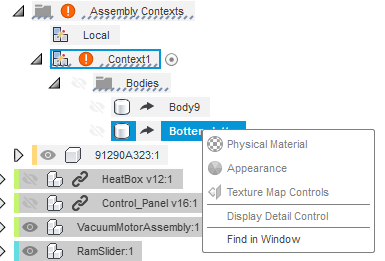
3) I really do not know what to do with the information displayed in the browser (se attached image). If there is an error (context broken)... now what? No valid option what to to with this. No highlight on WHAT the connection is between "Body 9" and.... I dunno, its gone. An option to "forget/delete/break" context would be nice. "Activate context" does not help since the reference is gone and no new options that allow to fix the issue appears. A continuation from my example: "Plane 2 (pin) needs Points 23, 24, 16 (bracket_rear) but are missing/lost": Create new from cache? or create new manually? or break connection (fix later, use cache with warning for now)?


4) Having used CAD for many years I know the value of knowing where the "origin" is and great to reference to/from when creating geometry BUT in an assembly the origin points for any component is totally irrelevant for the user, It might be nice for visual reference but since actual geometry is used to make joints/alignments etc that is all I should be concerned with (and where I am in the hierarchy). If component A is supposed to move with component B than select appropriate geometry on A then [Function pair/parent/joint], select geometry on B, A is now parented with B. If A is supposed to point at C while attached to B, select appropriate geometry on A, select appropriate geometry on C, choose "look at constraint (or whatever works)". All of this is saved in the assembly because it is only here that this information is relevant.
 If I want to use some geometry from A to design B; activate/create B, choose geometry on A, copy geometry to "XREF" folder in component B, save link. Simple 😉 Forcing the user to be concerned of more CAD-technical stuff than this is WIP-features that is confusing and should be removed in the end.


I think EIP is great and I'm looking forward to a more "slimmed" version.

Reply
Reply
0 Likes
Message 32 of 50

gautham_kattethota
Autodesk
Autodesk

Hi,

Thanks for your feedback. I will try to address your observations/concerns:

  1. In Fusion360, new components (local or exterrnal (XRef) components) are not constrained to the parent assembly by default.  They have to be properly constrained to the parent using Joints.  That might be the reason why you see components moving around. 
  2. The Assembly Contexts folder will have one local context and zero or more numbered Contexts.  A local context is similar to opening that XRef in its own tab - where you neither see the rest of the assembly nor the positions imposed by the assembly.  When you activate the local context you will see these two behaviors.  
    A numbered Context is created when a geometry or position is referenced from the parent while in EIP mode.  It creates a corresponding context in the parent assembly's timeline, which gives the context a timeline driven point in the assembly's history where the context was created.
  3. The image attached points to a broken Context feature.  A context feature, if not healthy, could be out of date with respect to the parent (blue icon on browser entry) or Broken (red icon on browser entry).  When broken, it means that the corresponding link in the assembly has been deleted.    You can right click on the Context entry and invoke the Delete command.  It will retain the referenced bodies and make them local to the XRef so that the features in the XRef that use those bodies will continue to work.


Hope this was helpful .  Please reach out if you have more questions or comments.  We appreciate your feedback.


Regards

Gautham


Gautham Kattethota
Software Development
Reply
Reply
0 Likes
Message 33 of 50

kgrunawalt
Autodesk
Autodesk

Hi,

Thanks for the complement and very thoughtful critique. You are seeing that seems wrong is intentional and explainable behavior, but that doesn’t make it intuitive and helpful! Fusion has some gaps that we are working on filling. Edit in place (EIP) does not introduce these issues, but it makes them more immediate. Below, I’ll give a brief history of Fusion assemblies because it helps explain the gaps. Then, I’ll try to address your points.

Note: I tend to use “XREF” to mean inserted model under parent assembly. XREF is short for external reference which is much more generic than this meaning, but it has become associated with inserted models in Fusion.

History

Fusion started as a pure direct modeler in a single model file (no xrefs). The goal was to have very fluid in-place building and manipulating of geometry and parts.

When we implemented parametrics and added the timeline, we kept this direct top-down fluidity by having assembly-focused features (inserts, joints, moves) in the timeline. This unique parametric assembly approach allows parts and assemblies to be built in-place and evolve together with cross-part references using computed positions. This avoids all the complexity that other modelers have introduced to support top-down workflows. This was really new to CAD and still is the most powerful top-down parametric approach available, but at the time it lacked xrefs and support for distributed building of models bottom-up.

At the same time, Fusion implemented fully flexible assemblies where each occurrence of a part is free to move and isn't automatically rigid within its subassembly. Traditionally, CAD has made subassemblies rigid in the context of the parent assembly. Each model file is one assembly level. They later added flexibility overrides that exposed subassembly freedom within the parent assembly (with sometimes unexpected results). Fusion started with fully flexible assemblies and used joints to define how things should move very explicitly. Joints help use control degrees of freedom parametrically which is important to a parametric assembly. Joints also can impose rigidity when operations do not require them to move.

Flexible joint-based parametric assemblies were brand new with Fusion and this newness left some gaps in functionality and clarity, especially for experts in other systems:

1. Cannot create distributed (multi-model) assemblies. This was addressed years ago with xref insertion.
2. Cannot edit inserted models directly. This is addressed by EIP this year (finally).
3. Joints can be frustrating. We have made recent improvements to the Joint command and you will see more in the near future.
4. Inserted and built-in components are disconnected (free floating) by default. This causes headaches and leads to your first point.

Point #1

You say "if I create a body/component at a specific place at any level in the hierarchy of an assembly and it moves around as a result of me changing level (or between components) seems like a serious bug".

What is really happening is that you have created a component occurrence that is not connected/constrained by a joint and it is getting left behind. This is always a bad practice in a xref subassembly in Fusion. Unfortunately, Fusion makes this really easy to do! Components that are built in-place look assembled, but they are actually not constrained/connected by default. So I won’t argue that there isn’t a bug – but the bug is that Fusion makes it easy to get in this situation without making the reason obvious.

When the timeline is recomputed, components are built where they should be built, but downstream features and parent timelines see them as completely free floating unless joints are added. Grounding, unfortunately, is not the right answer (I won’t go into detail here). What is needed is a joint that connects each new component occurrence to the assembly -- somewhere in the timeline of the model where the component was added. For example, if a new built-in-place component should be rigid WRT its parent component, you should add an as-built rigid joint between it and its parent. This is a best practice preached in many videos, but Fusion itself does not make this clear.

Un-jointed components are “left behind” when they are added to a subassembly after parent assemblies have already inserted and positioned the subassembly with joints and position features. When the parent assembly is updated to use the new subassembly version, the positioning already in the parent does not apply to the new free-floating components. They are left behind. Fusion’s Move command will move un-jointed children of a selected subassembly for convenience. This actually hides the fact that Fusion subassemblies are completely flexible by default. It was a partial solution that can lead to wrong assumptions.

Before EIP, this problem could happen by opening an xref’d subassembly directly, adding a new un-jointed component, and then updating a parent assembly to the new xref version. The update can result in the un-jointed component appearing to move. It is actually being left behind as the parent’s positioning of the subassembly is applied. You can usually see this by rolling back the parent timeline to where the xref is inserted. If the new component was constrained by a joint in the subassembly, it would move along with rest of the subassembly. With EIP, the same exact thing is happening much more easily. EIP makes the gap more obvious.

Best practice: always join new component occurrences to their assemblies! You should never insert a subassembly that has free floating components. Fusion does not yet make this clear. I should not say “never” since you can always edit the xref and add joints later – but the sooner you add them, the fewer surprises. In EIP, you can now add joints to help with this. When you do, you’ll be switched to the “Local” context automatically. Why? See answer to Point #2.

Point #2

What are the Assembly Contexts in the browser? What is the meaning of “Local Context”?

First, the Local Context is nothing new really – it is just now visible in the browser so that it can be activated along with other Contexts. It is the Context defined by the model itself, not by a parent assembly. All component positions seen in Local Context are determined by the active timeline. What is new is that there can be other Contexts that impose positions computed in other assembly timelines. When these Contexts are active, positioning is restricted because it is determined by a particular parent model’s timeline that is not currently active.

When you use the Joint command in EIP, Fusion switches automatically to the Local Context because joints can impose new positions (even as-built joints in some cases). This may not be very obvious (perhaps a new gap to fill). Simple rule: operations that move things, including adding joints, must be done in the Local Context because that is where the edited model can control positioning.

Assembly Context, as a term, makes sense because we need the both local Assembly Context representation (for activation) and parent Assembly Contexts (for activation and caching referenced geometry and positions). These are related but local not an XREF. Also, XREF as a term is already strongly associated with inserted models (children). Technically, you are right in that parent Assembly Contexts are external references (XREFS).

You can break link to a whole Assembly Context today, but you cannot break link on specific references as you note. This is a good idea for the future.

Point #3

Assembly Context status confusion. An Assembly context can be Out of Sync (blue “i”) or broken (red “!”). What do these mean?

Out of sync (OOS) means reference geometries or positions have changed in the parent. This includes positions imposed on the subassembly’s children – even if those positions are not used in features created in that context. If you synchronize a context in the browser of the opened model, the cached references are updated from the latest context parent version and the model is recomputed to use these references. This does not cause the parent to consume the updated xref. That has to be done from the parent after saving the updated subassembly. You can also synchronize from the parent either via browser or the Context Feature in the timeline. They will both have the same blue icons. This synchronization will both update the xref and the parent in one step.

Broken means that the Assembly Context’s source/parent model has been lost. This can happen if information is deleted that connects the two models:

1. The xref link from parent to xref model has been deleted
2. The Context Feature in timeline of parent has been deleted or an old version has been promoted that does not have the feature
3. The parent model itself deleted

Cause #2 bears some explanation. The Context Feature in the parent assembly is key to remembering the context used to do editing in-place. It remembers the specific path selected from the browser to begin editing (there can be multiple paths to the same child). It remembers the point in the parent timeline defining the state of the parent used to edit in-place. This feature can be deleted explicitly, causing a broken context in the xref.

Point #4

I need a little clarification on this point to address it. You are right that quite often the coordinate system of a part is not that important in an assembly context. Fusion allows creating parts in-place and their default CS is often just the same as the parent. For example, extrude new component might create a block off in space aligned with selected profile, but the new component CS might be elsewhere aligned with whatever component is currently active (the new component’s parent).

I think you are getting at some of the issues I raise above. Fusion is creating components in-place in an assembly hierarchy. This hierarchy does not impose any restriction on motion in Fusion. Those restrictions are created by joints using specific geometry. Joints are located in the hierarchy at the lowest common component shared by the two operand paths selected to form the joint.

Subassemblies that are designed to be inserted into other models should have every component occurrence connected directly or indirectly to the root component of the subassembly. I can’t think of any subassembly that should have floating components. If you go back to an inserted subassembly and components without connecting them in some way using a joint, you are likely to see them be “left behind” when you return to the parent assembly and update it. Fusion makes this mistake too easy today. EIP makes this even easier. This is an area for improvement.

I hope this helps! I expect I’ll be editing this to clarify things.

Cheers,

Katrin

Reply
Reply
0 Likes
Message 34 of 50

Anonymous
Not applicable

Hi @helfenj @kgrunawalt ,

Please help:

I'm trying to create a Joint Origin using the Edit In Place command but I can not do that. I finally have to open the XREF in a second tab to create the joint origin.

Reply
Reply
0 Likes
Message 35 of 50

kgrunawalt
Autodesk
Autodesk
There are commands not yet enabled in EIP and Joint Origin is one, unfortunately. They will be added in future updates.
Reply
Reply
0 Likes
Message 36 of 50

Henrik_Horlin
Enthusiast
Enthusiast

oh, wow. lots of text. Some of it helped, I'll clarify some of my points since I may have been somewhat vague in my presentation. 

 First I'd like to say that I am one mind among millions of other uses and do not claim to have any "correct" or "best" answers. I have used CAD many years, zero years in developing CAD software, I do know that it is very hard to develop software and I imagine that there are 1000+ hours of thinking/testing behind most features, so all I do is try to explain my perceptions and viewpoint on how I would understand something better. I might be "old in my ways" but I hope to grow with the capabilities of the tools available.


As I understand your first point is that components should not change place when changing level in a hierarchy as a feature but more an unfortunate effect of the nature of how Fusion works and you are working to fix the issue without the user "forgetting".


 When writing this response it occurred to me that Fusion is more "timeline"-centric than browser-centric like me. I've studied Interaction design for three years and worked with it on and off for a couple of years now, as an ID/UX-person I can say that there is a discrepancy between what Fusion wants (how it works) and what is shows as useful/important. The Browser is much more prevalent (more screen space) and displays more relevant information about the entire structure than the timeline does, it also has more functions/tools available to affect the work and how to display the work. But the timeline is king considering what is possible and not.

 If I can create a component in a sub-assembly (as seen in the browser) and not have an automatic logical connection to the closest parent than the browser in Fusion does NOT represent a hierarchy that is true until a joint is placed by the user.  I'd recommend automatically applying a "as built" joint between the origin of the component created/imported to the closest parent layer origin in the hierarchy (at least as a quick-fix) or, at a minimum, assign an icon/color to the component in the browser warning/indicating that it has no reference other than to assembly origin (if it does not lay in "root").

 An idea could be to implement a toggle-activated branching timeline, every component has its own timeline and if operations are dependent of other components it shows them side by side and where the dependencies link.


At first I did not understand why there needed to be a "context" folder in a component since an assembly is made up from components that are "their own entity" that is separated from the assembly, BUT since one can use geometry from other components to create new geometry in a component there has to be a link to where the reference comes from, I get that now.

 I do wonder how you would differentiate between the different contexts (because I can have several) in the same part if there already is "derivative parts"? What is the practical up-shot from this feature/function compared to having a derived part? Is it something that is going to morph into a new version of derivatives later on or is it a more dynamic WIP tool or...? Is it only for placement? (haven't had time to look into this)


Would it be possible to turn OFF the "context" function? That it doesn't reference another component at all, just copy the geometry and forgets where it came from? Because if there is a lot of switching positions, components and concepts (I do this all the time) the broken links pile up pretty quickly and since right clicking and choosing delete does not work (yet) because it is not an available option, I have to open the component in a new tab, delete the link there and then save it again. Not optimal.

And! Aaaaand! some sort of "freeze all components right where they are now"-function. I have so many "capture position"-icons in my timeline.... gaah! If I could delete all previous positions on all... really nice.


Whenever there is dependencies on such a granular level as individual points/edges/faces it would be REALLY nice if there was a good way of showing exactly what is connected to what, and have the ability to manage those connections with simple commands like "Delete" and "replace with".


My ramblings about "origins" in point 4 was a convoluted way of saying that I do not want to be bothered with "underlying requirements for the software to work" to get a reliable result. But since the in-depth explanations and me thinking a bit more I really do not see any more unanswered questions/thoughts about that except one statement:

 If there are consequences of inaction in a choice (such as applying a joint or not) that can contribute to "unexpected behavior" (components moving around) there should be some indication between the outcomes so that I can see what could contribute to the unwanted result. Also good to reference an actual indicator in educational videos etc.


Reply
Reply
0 Likes
Message 37 of 50

kgrunawalt
Autodesk
Autodesk
Hi again,

Browser vs Timeline

The timeline generates what is in the browser. The browser is the resultant state of the model as computed by the features in the timeline. If you roll back the timeline, the browser changes to reflect the state at the current point in the timeline.

So Timeline --> Browser.

Some commands available in the browser are short-cuts to editing the timeline. For example, Delete or Remove a body. Delete removes the timeline feature that created the body. Remove adds a feature at the current point in the browser that removes the body from that point on. You could roll the timeline before the Remove and see the body again.

Some commands in the browser just tweak attributes not controlled by the timeline (visibility).

Positioning Summary

Regarding component positions changing, you are right. This issue is a consequence of adding new un-jointed components in existing subassemblies that have already been moved by joints and positioning by the parent. The new un-jointed component is not automatically positioned by the existing moves in the parent timeline. It gets left behind. The solution is to add joints to the subassembly. You can add joints to the xref at any time in the process and update the parent to fix things.

Context vs Derive

Sometimes derive is better than contexts if you want to think ahead and build a skeletal part for reference. You can then derive what you need into each part directly from a skeleton. The top assembly then is a little simpler and currently easier to update. For convenience you could insert the skeleton part into your assembly along with the parts that derive from the skeleton. Then you can use EIP to edit the skeleton easily and then update all the parts that use it from the parent. This takes more effort to set up, but makes for a simpler top assembly timeline.

Contexts allow more direct referencing of the current state of the whole assembly (positions, geometry) while you are building a subcomponent in EIP. This is very direct and powerful, but there are some limitations. They are less easy to update (we are working on that) and don’t provide parameter access.

Short answer: sometimes derive is the right choice – especially if you want to centralize a skeleton for reference in a part that isn’t the parent assembly of the parts that reference the skeleton. We will continue refining Contexts to make them easier to work with.

Other Suggestions

“it would be REALLY nice if there was a good way of showing exactly what is connected to what”

“If there are consequences of inaction in a choice (such as applying a joint or not) that can contribute to "unexpected behavior" (components moving around) there should be some indication between the outcomes so that I can see what could contribute to the unwanted result”

Good points!

Reply
Reply
0 Likes
Message 38 of 50

Henrik_Horlin
Enthusiast
Enthusiast

A "positioning summary" (when not using joints) would be great because when in "exploratory stage" of a project I really do not know where something is supposed to go (or even if it is the correct thing) in the beginning. If I have a handful of components that is supposed to go into a space and it is not clear how, there is going to be a lot of moving around, aligning and moving some more... As soon as I'd like to check a simple 2D envelope with a sketch I need to capture the position. If I have to lock any component to a specific place with a reference hole or something similar I have to break/remove joint if the reference is on another surface/component to move it. If I need to move the reference hole/edge/distance on the same planar face, yes, joints will probably work most of the time.


 Something like "move history marker here and remove all captured positions before this one" would be nice but I believe that removing the "capture position" icon in the timeline is better. I (as a end-user) can not think of a scenario where I would want to use reference from previous positions of a component. If a reference from a previous position exists it is either irrelevant or broken anyway. Or am I missing something?


Maybe invoke an "exploratory mode", a temporary disabling of design history and bake what ever happens in this state as "dumb" un-referenced geometry. Or have a translation/rotation property window that have a history-list of all positions (if that is needed).


All of this to say: it is difficult to find the relevant "capture position" icon in the timeline to modify a position parametrically if joints is to restrictive to use. I'll try to use joints more and see if I'm just old 😜

Reply
Reply
0 Likes
Message 39 of 50

Florian__
Advocate
Advocate

The edit in place function is great. But there's one issue. If you edit a part in place and it is open parallel. Imagine we editing the part in place and afterwards, we close the parallel open part. Then it can happen, depending to the preferences, that the parallel opened part will autosave and the edit in place changes are overwritten. Would be great to get a message which changes you want to have. Or something like that.


Another thing would be quite useful that you can easily navigate to the location of the part threw the context menu or you can at least easily see its location path. A lot of time searching for the location of the included could be saved.  If that's not part of your work please forward it.


Reply
Reply
0 Likes
Message 40 of 50

gautham_kattethota
Autodesk
Autodesk

Hi Florian,

Great observation. Yes, with Edit In Place, users can easily get into situations where the part is open in its own tab, while the same part is being edited through Edit in Place through an assembly, in the same session.  We need to improve the user experience so that users do not unknowingly make changes in the part in both places.  We are looking into this.

Regarding your other observation, I guess you are asking for a better way to know which folder/project the contents of a distributed assembly (file with external references) came from?  If this is what you are reporting, then yes, I understand, that will be very useful to know.  I will forward it to the right team.


Regards,

Gautham


Gautham Kattethota
Software Development
Reply
Reply
0 Likes