In my most recent test configuration, I got the following error message:
Warning: Dissimilar Fluids
Could not assign Boundary Conditions!
Two different fluid materials are touching
Check material assignment to ensure that all contacting fluid parts are assigned the same fluid material
Note: that non-fluid material types (such as solids and distributed resistances can contact fluid parts.)
I found this information:
Multiple Fluids
https://knowledge.autodesk.com/support/cfd/learn-explore/caas/CloudHelp/cloudhelp/2019/ENU/SimCFD-Us...
Autodesk® CFD has the ability to handle multiple fluids in one model. Note that fluids with different fluid materials cannot contact one another unless one or more is a distributed resistance. Non-distributed resistance fluids can be connected thermally (separated by a solid material).
To implement multiple fluids, assign the fluid materials as appropriate, and ensure that different fluids are separate by solids or voids.
Here was an earlier post, with a similar question. But I still am not clear on how to ensure that different fluids are separate by solids or voids and then be able to assign materials to them? “Void” air gap?
https://forums.autodesk.com/t5/cfd-forum/mixing-2-fluids/td-p/5376059
apolo.vanderberg
Autodesk Support apolo.vanderberg in reply to: JReinante
11-03-2014 11:14 AM
JR,
Some of the confusion of this comes from the fact that for SimCFD if you have 2 fluids mixing such taht you have A coming in one sectino and B coming in another, the way we set this up is via Scalar mixing.
What this means is that the entire domain will have a single material (we'll call it "Mixture" as an example).
Then if you modify this "Mixture" fluid you would set the Density/Visc/etc to be table driven and to Vary with respect to scalar
Set up the table as such
Scalar Density
0 ## kg/m3 of Fluid A
1 ## kg/m3 of Fluid B
Then on all inlets you will specify whether Scalar 1 (Fluid B) or Scalar 0 (Fluid A) is coming in to the domain at that opening.
Be sure to turn on Scalar mixing under the Advanced section, but otherwise this should get you moving forward.
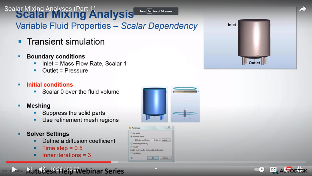
There was a very good webinar that Marwan and Amal prepared.
Scalar Mixing Analyses (part 1)
https://www.youtube.com/watch?v=nlr8CHQhigs
Mixing tank – Water and Methane
The information on Scalar Mixing and settings was valuable and I understand most of that.
It might help me, if you could explain how the mixing tank with three inlets was constructed in CAD to allow two different fluid materials to be assigned and mix without touching?

Mixing Tank as Outline
In this screen shot please note that the visibility of tank body is set to Outline, both Water and Methane inlets appear to be constructed as one pipe that protrudes either side of the upper tank. This is where I am confused. I am thinking of two inlets welded to the tank which is empty. How can two dissimilar fluids be defined at both inlets of the same pipe without creating problems? How can either fluid enter the area within the tank and mix if they are contained inside a pipe? Then there is the drain pipe, it would have a fluid mixture of Water and Methane. Would you only need to define the outlet pressure at the discharge of the pipe and not the material?