I would like to have consistent dimensions on all drawings including across continuation drawings.
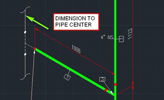
When a valve or a fitting is on the same Isometric it is dimensioned to the IP point and connecting lines are dimensioned to the centerline of the connecting pipeline, but when there is a continuation drawing the dimensions finish at the end of a pipe or fitting, as a rule you do not terminate a dimension at a welded or screwed joint.
The attached image explains this better

