@JohnC_ISM wrote:
i thought the screenshots were pretty self explanatory. ....
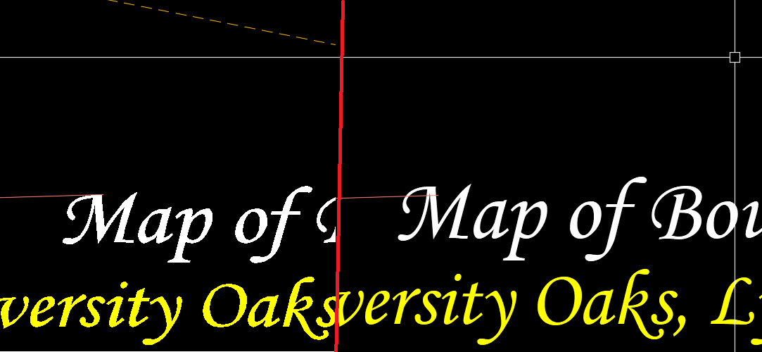
I didn't get what you were talking about at first, either. Studying the images further:
In the images, I assume one side of the heavy red mid-line is "right" and the other is "wrong," though it's not identified which is which. I think it's the right side in ex2, because of the boxed-in bits that are apparently pointing out what I assume must be the "wrong" result. There is a difference in Y-axis-direction position between certain things in one side vs. the other.
In ex1, I assume the purplish-brownish line at upper left is a constant, and gives something to compare the position of the big M in the text to, to see the difference. But if the right side is "wrong," it's higher, rather than lower as described, so maybe it's the left side that's "wrong." And in the left side, what looks like a drag line is visible at the top, apparently in mid-command, so what can it tell us?
In ex2, if the boxed-in bits in the right side are "wrong," there's a very much smaller Y-coordinate difference from the left side [but there is a difference] than the difference in ex1.
But if my interpretation of what the images are meant to show is correct, we're still missing the more crucial parts that even a drawing file might not answer. We can't tell what you gave it as start and end points for the Move displacement, what your Osnap setting was [if any], what Coordinate System and/or view direction you're in, etc. That's why a video might be the most helpful thing, preferably including the UCS icon and enough of the Command line to see what commands/options you're using.
Kent Cooper, AIA 


