Community
- Forums Home
- >
- AutoCAD Electrical Community
- >
- AutoCAD Electrical Forum
- >
- Ways to use Terminal Blocks ...
AutoCAD Electrical Forum
Welcome to Autodesk’s AutoCAD Electrical Forums. Share your knowledge, ask questions, and explore popular AutoCAD Electrical topics.
Turn on suggestions
Auto-suggest helps you quickly narrow down your search results by suggesting possible matches as you type.
Reply
Topic Options
- Subscribe to RSS Feed
- Mark Topic as New
- Mark Topic as Read
- Float this Topic for Current User
- Bookmark
- Subscribe
- Printer Friendly Page
Message 1 of 20
07-13-2014
08:29 AM
- Mark as New
- Bookmark
- Subscribe
- Mute
- Subscribe to RSS Feed
- Permalink
- Report
07-13-2014
08:29 AM
Ways to use Terminal Blocks ...
Using ACADE 2014 (new user). I'd like to be able to show the physical connection points to terminal blocks directly on my schematic. As I stated, I'm new to ACADE 2014 and very new to Terminal Strip Editor (TSE). We use primarily single level WAGO terminal blocks like this:

We reference the physical wire connection points starting at 1 at the top of block (at the right if mounted horizontally). So, for block 1, the top connection is referenced as 1.1 and the bottom connection as 1.2. Sometimes we use triple or quad blocks and the numbering works the same (1-3, 1-4, from top-bottom (right-left)).
So, on a schmatic I'd lke to see something like this:

So this says that wire 219 goes from connection 2 on F5 to terminal strip TB02 : terminal block 3 (wiring position 1 [3.1]) and comes out on terminal block 3 (wiring position 2 [3.2]) which has a connection to CBL20 conductor 3. This provides all the information needed for the panel builder directly on the schematic.
Diagrammatically this seems to work fine but when I try to generate the terminal strip layout, I have some problems. First, ACADE doesn't know about my naming convention, so it thinks 3.1 and 3.2 are 2 separate terminal blocks.
To my specific questions:
1) Is there a better (more standard) way to represent the terminal block connection information that I want on the schematic that won't cause ACADE problems and that will save me time?
2) I'm just learning TSE, so maybe there's a way within TSE to combine 3.1 & 3.2 into a single block. Is that possible?
3) Is there a standard method within TSE to document the physical connection point information for each terminal block? If this is done, is there some way to show that physical connection info on the schematic via some type of terminal block symbol (or attribute info already present on the block)?
4) I know jumper information can be supplied in TSE but how do you show jumper info on the schematic automatically? Again, trying to show the bulk of the info on the schematic to make panel building as easy as possible. Here's an example:

In this case, Wire 228 coming from T1:X2 connects to strip TB02 at block 5.1. Block 5 and 6 are jumpered together (as you can see in the WAGO layout above). So Wire 228 feeds TB02:5.2 and TB02:6.2 (using my naming convention) and these blocks have direct connection to CBL20.4 (for 5.2) and CBL21.4 (for 6.2). Is there a more standard way of showing this information? I manually labeled the wire between blocks 5 & 6 with a JUMPER description so automatic wire numbering would just skip this wire. Again, this provides the info I want but I'm not documenting things in a way that allows ACADE to do more things automatically for me to save me time. What would be a more standard way of showing this information?
Really appreciate any help.
19 REPLIES 19
Message 3 of 20
07-14-2014
12:31 PM
- Mark as New
- Bookmark
- Subscribe
- Mute
- Subscribe to RSS Feed
- Permalink
- Report
07-14-2014
12:31 PM
Hi Clyons,
If you give one of the terminals 2 levels (Edit the teminal Properties in the TSE) you can "Associate" the levels together. ( making one terminal block on the BOM).
I think one of my older posts has nice screenshots for this.
Let me check for it, and i'll post a link, if not i'll take new screenshots 🙂
Regards,
James
James Alger
(I'm on several hundred posts as "algerj")
Work:
Dell Precision 5530 (Xeon E 2176M)
1tb SSD, 64GB RAM
Nvidia Quadro P2000, Win10
(I'm on several hundred posts as "algerj")
Work:
Dell Precision 5530 (Xeon E 2176M)
1tb SSD, 64GB RAM
Nvidia Quadro P2000, Win10
Message 4 of 20
07-14-2014
12:59 PM
- Mark as New
- Bookmark
- Subscribe
- Mute
- Subscribe to RSS Feed
- Permalink
- Report
07-14-2014
12:59 PM
Hi Clyons,
I have no idea where on-line it is. So New Pictures! 🙂
ok, First thing you can edit the Block Properties when you insert the schematic terminal or you can edit it after the fact in the terminal strip editor.
Either way you need to add 2 levels to one of the terminals ( Add it to 3.1).

After that you select the two terminals ( 3.1 and 3.2), make sure you select one level from 3.1 and then select the terminal on 3.2) select assoicate terminal. (note: this picture was done AFTER they were assoicated (thats why 1 & 2 are already together) (see picture 3 for the "Before" image)

After that the Assoicate Terminal Dialog box appears, at the side browser (where it says Terminals) select 3.1 and go to level 2. Then select Assoicate. It should pull 3.2 into the 3.1 terminal. It leaves an empty terminal behind.

For cleanup remove the extra spare terminals that are generated (they are leftover empty terminals) and add in any hardware you need llike endplates, anchors, etc.
I hope this helps,
James
James Alger
(I'm on several hundred posts as "algerj")
Work:
Dell Precision 5530 (Xeon E 2176M)
1tb SSD, 64GB RAM
Nvidia Quadro P2000, Win10
(I'm on several hundred posts as "algerj")
Work:
Dell Precision 5530 (Xeon E 2176M)
1tb SSD, 64GB RAM
Nvidia Quadro P2000, Win10
Message 5 of 20
07-20-2014
04:03 PM
- Mark as New
- Bookmark
- Subscribe
- Mute
- Subscribe to RSS Feed
- Permalink
- Report
07-20-2014
04:03 PM
There is a way to show the information you want while only using one terminal...
Insert the terminal as normal and fill in the data in the dialog box. Before you click OK or OK-Repeat, click on the Show/Edit Miscellaneous button.
The fields you are looking for here are the X?TERMDESC## ones. fill in the appropriate values in the correct fields.
X1 is for wires connecting from the right.
X2 is for wires connecting from the top.
X4 is for wires connecting from the left.
X8 is for wires connecting from the bottom.
Exit out of the dialog box.
Now you need to right click on the terminal, select the attributes sub menu, then the List/Edit command.
Scroll through the list and find the X?TERMDESC## attributes and click on them once so that a star appears next to them. Exit out of that command.
You should now be able to see the information on your screen, but you many need to adjust the attribute layout and sizes.
If it is a standard practice in your company to show terminals this way, then I would suggest editing the blocks themselves to show the attributes where you wish them be. Attribute visibility can also be set when doing this.
One thing to note is that ACADE uses these attributes to store the Internal/External values when they are set.
Regards Brad
>
Brad Coleman, Electrical Draftsman
Did you find this post helpful? Feel free to Like this post.
Did your question get successfully answered? Then click on the ACCEPT SOLUTION button.
Message 6 of 20
07-21-2014
08:11 AM
- Mark as New
- Bookmark
- Subscribe
- Mute
- Subscribe to RSS Feed
- Permalink
- Report
07-21-2014
08:11 AM
@Icemanau wrote:
The fields you are looking for here are the X?TERMDESC## ones. fill in the appropriate values in the correct fields.
And therein lies the problem, I suspect. Having to manually enter all of that would get tedious, not to mention it adds an opportunity for human error. If there was a way to push the information into those attributes automatically, that would be better. Right?
Not to mention that if you needed to relocate that terminal to another strip/bock, for example, then those hand entries have to be hand edited. If they were system controlled, they could be made to update along with everything else.
But I think this is on the right ttrack. Interesting discussion.
--------------
Joe Weaver
Principle Associate Engineer - Nashville Electric Service
P&C Committee Chair – SDS Industry Consortium
Joe Weaver
Principle Associate Engineer - Nashville Electric Service
P&C Committee Chair – SDS Industry Consortium
Message 7 of 20
07-31-2014
02:06 PM
- Mark as New
- Bookmark
- Subscribe
- Mute
- Subscribe to RSS Feed
- Permalink
- Report
07-31-2014
02:06 PM
Go to schematics edit/components menu > terminal: mark internal external connections. You can turn on the E and I attribute to have it displayed directly on schematic. External is equivalent to right side and Internal is equivalent to left side.


Message 9 of 20
08-02-2014
07:54 AM
- Mark as New
- Bookmark
- Subscribe
- Mute
- Subscribe to RSS Feed
- Permalink
- Report
08-02-2014
07:54 AM
OK, just getting back to this. Thanks for the various ideas but I'm still not seeing a clean solution that provides what I need without requiring me to do LOTS of additional work. We can have 100's of terminal connections and having to add levels and associate everything I think will just take way too long.
I kinda like the method of entering the information into the X?TERMDISCnn attributes. Showing those attributes does appear to provide a way to show the info I want by only using a single terminal symbol (but I'd need to create a custom symbol that automatically sets the display up the way I'd like to see it vs. having to manually choose to show the X?TERMDISCnn attributes and size & locate them properly). However, it's certainly painful having to enter all this information free-form using the attribute editor. And ACADE is not providing any checking of this information, so human-error will definitely creep in which will most likely cause all sorts of later problems. And I'm not sure if entering all the X?TERMDISCnn information manually will allow TSE to properly create the terminal diagrams. I haven't yet had the opportunity to physically try it but I will and will report back. The terminal symbols are carrying these X?TERMDISCnn attributes, so there must be some way that these atrributes are automatically filled-in when dealing with terminals. How is that supposed to work? Is there some way for me use existing code within ACADE to allow me to get the connection information more automatically entered?
Can someone explain the internal/external connection method a bit more? Feel a little stupid, but I'm just not getting it. How does the internal/external definitions find its way into the attribute fields? This looks like it has some promise but again, it's just not sinking in.
Regarding the last post by ccad2509, is that supposed to be a diagram using the manually entered x?TERMDISCnn attribute method? One issue I see is that there are still 2 terminal block symbols which is going to cause problems with TSE just like my original method. And the terminal block diagram doesn't provide the connection info, which is really what I'd like to see.
One last random thought, maybe a way to address this would be having both parent & child terminal symbols (this would an approach that is consistent with other parent/child symbols options). The parent could be processed by TSE as a block definition but any children would just be connection points that point back to a specific block. If something like this were supported, then you could create the exact diagram I'm looking for and TSE could gather all the necessary information straight from parent/child symbol definitions. Would something like this make sense?
Really was hoping all of this would be easier. I think what I'm doing is pretty standard but the methods of handling this within ACADE don't seem to be very straightforward (or even possible).
Appreciate any help.
Message 10 of 20
08-02-2014
09:26 PM
- Mark as New
- Bookmark
- Subscribe
- Mute
- Subscribe to RSS Feed
- Permalink
- Report
08-02-2014
09:26 PM
Hi Clyons,
I’m afraid that there is no built-in support for designating individual terminal wire connections the way you seek. I've been using this software and others since 1991, and to be honest, I've never seen that level of detail on a terminal block symbol. You could do it with plain CAD, but then there is no intelligence to auto-trim wires, auto-tag, report generators, etc., all the things we love about the intelligent programs that are available now.
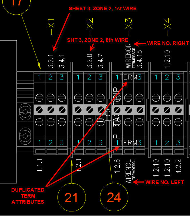
Most terminals are considered series terminals, so the potential usually passes through with no break in potential, thus the terminal designation is the same on both sides. But what has been done is to use a terminal symbol that forces the wire number to change on the other side. AutoCAD Electrical includes this symbol. Then TSE will show a different wire number on each side of the terminal, thus narrowing down to which side of the terminal each wire connects to. The wire number will appear by default, because displaying the wire number for a terminal is the default visibility state in TSE. You can also choose to display the wire type, and even where the other end of the wire connects.
I have modified the terminal symbols I use to display the TERM attribute at the top and bottom of the block. (see attached image) The default blocks only include one TERM attribute, in the middle of the block. These are series blocks that pass the wire number through. But if you insert the terminal symbol that forces a wire number change, the top and bottom of the terminal will be marked with a different wire number. Note the WIRENOL and WIRENOR attributes. These display either the same wire number on both sides, or a different wire number, according to which schematic symbol you chose, before you inserted wire numbers. But the TERM attribute is the same value. I only duplicated the attribute so it looked more "real-world" and to get it out of the way of my jumper-bar symbols. Those are smart jumper-bar symbols that I insert from my Panel menu, after I insert the strip with Terminal Strip Editor. The part number data is pre-loaded into the MFG and CAT attributes of the jumper-bars so all I do is insert them and the BOM generator will pick them up when it creates the report.
I know it is an adjustment, switching to intelligent CAD. With vanilla CAD we can do anything we want to a drawing, and there is nothing to prevent us from making mistakes. There can be as many standards as there are companies, using plain CAD. Intelligent CAD has to have some rules to play by and thus we often have to modify our company standards somewhat, if we are going to enjoy the many advantages that intelligent CAD has to offer. The developers have, over the years, used customer feedback to steer future enhancements, and they ultimately must make a judgment call as to what can be realistically achieved. But I have seen many, many customer ideas make it into the software.
One of my requests took 9 years, because of the level of overhaul it would require, and the potential for it to cause problems with other areas of the code. I had a different workflow that achieved the same goal, but the enhancement made it more streamlined. Just hang in there, but realize that there may be some areas where you have to compromise in order to realize the many benefits that intelligent CAD has to offer. In the event that your customer will not accept it any other way, you may have to resort to using the vanilla commands and live with portions of your drawings being unintelligent. But the net gain may still exceed what you could do with plain CAD.
Doug McAlexander
Design Engineer/Consultant/Instructor/Mentor specializing in AutoCAD Electrical training and implementation support
Phone and Web-based Support Plans Available
Phone: (770) 841-8009
www.linkedin.com/in/doug-mcalexander-1a77623
Please Accept as Solution if I helped you. Likes are also much appreciated.
Message 11 of 20
08-03-2014
12:37 AM
- Mark as New
- Bookmark
- Subscribe
- Mute
- Subscribe to RSS Feed
- Permalink
- Report
08-03-2014
12:37 AM
Unzip 2P_TERM.zip
Copy HT0002-VP.dwg to your library folder.
Default library folder path is \Users\Public\Documents\Autodesk\Acade {version}\libs\{library}\
Add a new icon to the icon menu (see AEMENUWIZ.mp4)
1. In ACADE type AEMENUWIZ
2. On the Select Menu File dialog box, select the menu file (.dat) to modify and click OK.
Your menu file should be already selected, so just click OK.
3. Select Terminals submenu.
4. Right-click on the Icon Menu Wizard dialog box and select Add Icon->Command...
5. Type name for the icon, e.g. 2points
6. Copy text from the Command.txt file to the Command field
7. Click OK
Test new terminal block.
Vladimir
Message 12 of 20
08-03-2014
04:42 AM
- Mark as New
- Bookmark
- Subscribe
- Mute
- Subscribe to RSS Feed
- Permalink
- Report
08-03-2014
04:42 AM
If terminal number on the HT0002-VP block is changed trough Edit Component dialog, only upper number changes.

Both numbers are 20.
In Edit component dialog change terminal number to 25:

Only upper number changed to 25:

File in attachment contains following lisp function:
termCopyProj - projectwide update of the lower number,
termCopyDrawings - update of the lower number in the selected drawings,
termCopyActiveDrawing - update of the lower number in the active drawing,
termCopyPick - pick terminals in the active drawing to change its lower number.
Appload TermCopy lisp file and call any of the functions.
Vladimir
Message 13 of 20
08-03-2014
06:09 AM
- Mark as New
- Bookmark
- Subscribe
- Mute
- Subscribe to RSS Feed
- Permalink
- Report
08-03-2014
06:09 AM
Doug,
If you look at Solidworks Electricals' terminal strip functionality I think you'll see that it natively supports what I want to do (plus it's really flexible so it can basically adjust to whatever company standards you want to throw at it). It lets you choose the connection numbering scheme you want to use on your blocks up-front and then it captures (and tracks) this information when terminal symbols are used and creates the terminal strip diagram accordingly. The schematic symbol is a single block that shows the strip number, block number & connection IN & OUT information in the format you pre-define (it also supports & displays installation & location information). We just had them in for a demo and I threw this problem at them to see how it would handle it. It seemed to work perfectly (but, of course, we don't have an actual demo version so I have not been able to really see if it does handle all this as seemless as the demo showed). We will have a demo version in the next couple weeks and I plan on digging into this completely to be sure it operates as expected. Yes, I understand that Solidworks Electrical is quite a bit more $$$ but that's not due to their "special" terminal block handling (have you seen their 3D panel layout capabilities, and extremely flexible report generator?). Isn't anyone at Autodesk watching their direct competitors to see if they have an implementation idea that makes more sense? If they do, just copy the idea and implement within your environment to keep it "yours" but don't drag your customers through the mud. EFFECTIVE, SIMPLE HANDLING OF TERMINAL BLOCKS IS JUST SO VERY IMPORTANT AND BLOCKS ARE USED IN JUST ABOUT ALL ELECTRICAL PROJECTS. Come on, we deserve better ....
I certainly understand the intelligent aspects of ACADE and that's why we're going through all this pain to reap the benefits of that intelligence. But, I don't really think you should have to give up on company standards when the standard is exactly what needs to be done to ensure your panels are built quickly & correctly. Tracking connections on terminal blocks is pretty standard stuff and being able to name those connections however you'd like shouldn't be viewed as a SPECIAL. It's not complicated and is exactly the information panel builders need to get panels built correctly without requiring them to look at multiple diagrams, reports, etc. and make conscious interpretations to "extract" the necessary information. And as a designer, you shouldn't have to jump through hoops (i.e. add levels & associate, manually add info to attributes, run external macros, create special symbol varients, create special reporting, etc.) to do things that need to be done anyway. The basic schematic & terminal strip/block diagram should simply provide the necessary information to the builders directly, NO HOOPS. It really seems crazy that after 20+ years ACADE has not been able to implement a terminal strip/block system that natively meets the needs. It's just not that complicated, look at how Solidworks is doing it!
Message 14 of 20
08-03-2014
09:20 AM
- Mark as New
- Bookmark
- Subscribe
- Mute
- Subscribe to RSS Feed
- Permalink
- Report
08-03-2014
09:20 AM
I was a Solidworks customer in the 1990s. We kept asking them to create a controls diagram software that would be compatible with their modeler. They said that they were working on it. We waited and waited and waited and finally went with AutoCAD Electrical for controls drawings, staying with Solidworks for modeling. We wanted one platform to do it all but we could not wait 15 years. Now they have the opportunity to look at all other software that has preceded their entry into the market, identify perceived weaknesses and capitalize on that. I would do the same if I were them.
But now that I have thousands of panels designed with AutoCAD Electrical I don't want to change. Inventor is a great modeler but those who have thousands of models created with Solidworks are also reluctant to switch. I understand that completely.
I like Vladamir's lisp. You can add it to the Startup Suite so it is always loaded and ready.
Doug McAlexander
Design Engineer/Consultant/Instructor/Mentor specializing in AutoCAD Electrical training and implementation support
Phone and Web-based Support Plans Available
Phone: (770) 841-8009
www.linkedin.com/in/doug-mcalexander-1a77623
Please Accept as Solution if I helped you. Likes are also much appreciated.
Message 15 of 20
08-03-2014
09:51 AM
- Mark as New
- Bookmark
- Subscribe
- Mute
- Subscribe to RSS Feed
- Permalink
- Report
08-03-2014
09:51 AM
It sounds like your company wants to know whether a particular wire connects to the top or bottom of a terminal. That can be accomplished with built-in features.
You can mark which side of a terminal is internal or external. You can assign this to the schematic symbol or wait until you are in Terminal Strip Editor (my preference). You can add which component the terminal connects to on the other end to the wire annotation on a graphical strip. This will certainly specify which wire connects to top or bottom (left or right if strips are vertical).
Hint: In TSE the terms internal and external are relative to your perspective. I just think of left as bottom and right as top when moving wires from side to side in Terminal Strip Editor.
If you dont want to clutter your graphical strips with annotation data you can use the common European method. Insert a terminal table which includes Installation, Location, Component on other end, Pin on other end, Wire Number, etc. This is very common in Europe, where DIN style terminals were invented. The table generator can automatically add a drawing per strip to your project and insert the tables for you. Your graphical strips can be placed into the panel layout and the tables serve as details of the graphical strips.
Doug McAlexander

Design Engineer/Consultant/Instructor/Mentor specializing in AutoCAD Electrical training and implementation support
Phone and Web-based Support Plans Available
Phone: (770) 841-8009
www.linkedin.com/in/doug-mcalexander-1a77623
Please Accept as Solution if I helped you. Likes are also much appreciated.
You can mark which side of a terminal is internal or external. You can assign this to the schematic symbol or wait until you are in Terminal Strip Editor (my preference). You can add which component the terminal connects to on the other end to the wire annotation on a graphical strip. This will certainly specify which wire connects to top or bottom (left or right if strips are vertical).
Hint: In TSE the terms internal and external are relative to your perspective. I just think of left as bottom and right as top when moving wires from side to side in Terminal Strip Editor.
If you dont want to clutter your graphical strips with annotation data you can use the common European method. Insert a terminal table which includes Installation, Location, Component on other end, Pin on other end, Wire Number, etc. This is very common in Europe, where DIN style terminals were invented. The table generator can automatically add a drawing per strip to your project and insert the tables for you. Your graphical strips can be placed into the panel layout and the tables serve as details of the graphical strips.
Doug McAlexander
Design Engineer/Consultant/Instructor/Mentor specializing in AutoCAD Electrical training and implementation support
Phone and Web-based Support Plans Available
Phone: (770) 841-8009
www.linkedin.com/in/doug-mcalexander-1a77623
Please Accept as Solution if I helped you. Likes are also much appreciated.
Message 16 of 20
08-04-2014
12:25 AM
- Mark as New
- Bookmark
- Subscribe
- Mute
- Subscribe to RSS Feed
- Permalink
- Report
08-04-2014
12:25 AM
Vladop thats exactly what i did make a single terminal into a dummy double terminal
what i was going to do next was to add 2 user sttributes which could be edited in dougs new favorite method "export to excel"
but then i though what about the attributes L01PINL & L01PINR in the Layout preview symbol which displays pin left and pin right details would they work in a terminal symbol ?
And tantalising enough it works you add these two attributes to new dummy double terminal
one way if you modify the details in the TSE it will write the information back to the terminal with these attributes added
and if you go edit component>block properties it will write back to the TSE

Message 17 of 20
08-04-2014
01:56 AM
- Mark as New
- Bookmark
- Subscribe
- Mute
- Subscribe to RSS Feed
- Permalink
- Report
08-04-2014
01:56 AM
In order to work properly L01LABEL, L01WIREPERC, LNUMBER, LTOTAL attributes must be also added to the block.
Vladimir
Message 18 of 20
08-04-2014
03:43 AM
- Mark as New
- Bookmark
- Subscribe
- Mute
- Subscribe to RSS Feed
- Permalink
- Report
08-04-2014
03:43 AM
Hello Vladimir
yes just did it on a WAG(wild **** guess) and even more surprised it worked
yes i will add the rest of the attributes in as i have a similar problem with my termional blocks
Message 19 of 20
08-04-2014
04:00 AM
- Mark as New
- Bookmark
- Subscribe
- Mute
- Subscribe to RSS Feed
- Permalink
- Report
08-04-2014
04:00 AM
If it is OK that terminal number e.g. 20 and connection points .1 and .2 are separate, than you don't need lisp.
In that case, move TERM01 attribute in HT0002-VP block to the place you want and delete TERM01_COPY attribute.
Lisp is used only to copy TERM01 value to TERM01_COPY, so that 20.1 and 20.2 are displayed.
Vladimir
Message 20 of 20
10-23-2017
02:37 AM
- Mark as New
- Bookmark
- Subscribe
- Mute
- Subscribe to RSS Feed
- Permalink
- Report
10-23-2017
02:37 AM
I used your TERMCOPYPICK to make a Upper / Lower switch for WDK terminals
(defun C:TERM_UP_LOW ()
  (while (setq SS (ssget "+.:E:S"))
    (setq BEN	  (ssname SS 0)
	  GET_UP  (C:WD_GETATTRVAL BEN "TERM")
	  GET_LOW (C:WD_GETATTRVAL BEN "L02TERM")
    )
    (C:WD_MODATTRVAL BEN "TERM" GET_LOW NIL)
    (C:WD_MODATTRVAL BEN "L02TERM" GET_UP NIL)
  )
  (princ)
)
Reply
Topic Options
- Subscribe to RSS Feed
- Mark Topic as New
- Mark Topic as Read
- Float this Topic for Current User
- Bookmark
- Subscribe
- Printer Friendly Page

