Linking data

Linking data

Arlene_Brown
Advocate Advocate
1,644 Views
7 Replies
Message 1 of 8

Linking data

Arlene_Brown
Advocate
Advocate

Hi there,


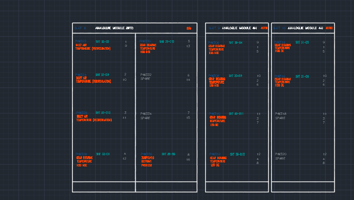
I am trying to link the field instrument tags and descriptions fields through my full drawing package which included P&ID, Block Diagrams, JB Wiring Diagrams and Control Panel drawings. So far I have managed to link tags and description fields in the P&ID, Blocks and JB Wiring. However I can't think how to link the tags and descriptions to the PLC cards channel symbols which means that there is risk of them being different if one is changed. The tag number for the PLC card ch is the address so can't link it to the corresponding field instrument tag and descriptions. Has anyone any ideas? Ideally I would like all duplicated data throughout the drawing set to be linked so that they are all aligned. 


Thanks in advance.

0 Likes
Accepted solutions (1)
1,645 Views
7 Replies
Replies (7)
Message 2 of 8

alds02
Collaborator
Collaborator

Please post a screenshot. I've linked P & ID items to components wired to PLC. But I never tried to get the PLC descriptions to update, if that's what you're describing.

0 Likes
Message 3 of 8

Arlene_Brown
Advocate
Advocate

Thanks for you reply.


See attached screenshot. I can link the field instrument tag and description at the bottom of the drawing to the P&ID components. However I can't think how to link the PLC component. I currently have the PLC component separate, so I need to update the descriptions separately. I have these linked to child components on an I/O list. You can see this also on the attached screenshot.


Regards


0 Likes
Message 4 of 8

alds02
Collaborator
Collaborator
Accepted solution

I can understand the first screen capture, but I don't understand the second. I'm attaching an example screen capture from a PLC schematic.Untitled.png

0 Likes
Message 5 of 8

Arlene_Brown
Advocate
Advocate

Hi there,


Thank you for your reply.


I accidently accepted the solution there. I have now linked the P&ID tag number to the panel component using the WDTAGALT field and so if I update the P&ID tag, the tag also updates against the panel components. However if I change the P&ID description it doesn't update against the panel component. Are there description fields linked to the WDTAGALT field which link to the original descriptions?


The other screen shot is just a separate drawing outlining the I/O lists for each PLC card.


Thanks and regards


0 Likes
Message 6 of 8

alds02
Collaborator
Collaborator

The last time I did a project that included P & ID was at a previous job, so I can't test this. However, I use the same process between pneumatic schematics and electrical.


So for example, if I Edit Component on a solenoid in a pneumatic schematic, and alter the description content, after clicking OK I am prompted to "Update Related Components?" with an option to update description as well.


Are you seeing anything like this? If not I can throw a new drawing into my current project and try it with some P & ID symbols.

Untitled.png

0 Likes
Message 7 of 8

Arlene_Brown
Advocate
Advocate

See attached screenshot. This is the message I get.


However I have it working now thank-you very much. When I update the tag or description of the P&ID symbol I get this message asking if I want to update the related panel component and it updates.


0 Likes
Message 8 of 8

alds02
Collaborator
Collaborator

Yes, I realize now that the message in my post wasn't quite right for you, because it was about an item on the same drawing (I had pneumatic "footprints" and schematic components on the same drawing).


The message you posted is typical.


Glad to hear you're all set.

0 Likes