custom wire numbering

custom wire numbering

rickstarosto4361
Advocate Advocate
2,483 Views
8 Replies
Message 1 of 9

custom wire numbering

rickstarosto4361
Advocate
Advocate

OH BOY? Potential customer as some unique drawing requirements:


Is this possible? Wire numbering (Alphanumeric)


           - first set of 2 digits will have equipment designation

                        *first 2 digits will be assigned by customer)

           - second set of 2 digits will be sheet(page) numbers

           - last set of digits, (3?) using X and Y grid the grid location

           Ex: 24DF15E


Maximum of 8 total characters

0 Likes
2,484 Views
8 Replies
Replies (8)
Message 2 of 9

jseefdrumr
Mentor
Mentor

To do this, you would make adjustments in Project Properties or in Drawing Properties. You'll need to change the format in two tabs in the relevant dialog boxes.


ACADE handles wire numbers via a string of 'Replaceable Parameters' (look that up in HELP for more info). For your needs, your format would be XX%S%N. You'll need to set this in the 'Wire Numbers' and 'Cross References' tabs.


The 'XX' represents the customer's equipment designation. %S will bring in the sheet number, and %N will bring in the grid location. (Note that using grids requires you to do certain things to ensure proper formatting in the 'Drawing Format' tab in this same dialog box.)


Jim Seefeldt
Electrical Engineering Technician


Message 3 of 9

rickstarosto4361
Advocate
Advocate

thanks for the response! i did the %S,  well i thought i did, %S works better than $S. the XX how does that work? that will not automatically populate? is there away if in my title block i have "machine code, attribute that when i add wires the motion of  adding wire number links to that machine code and then it goes through the sheet and rung?

0 Likes
Message 4 of 9

jseefdrumr
Mentor
Mentor

If you need it to automatically populate, you'll need to use one of the preset replaceable parameters. My recommendation would be location and/or installation, which are %L and %I, respectively. You would assign the location/installation values in each drawing's properties, and follow the formatting I outlined above (%L%S%N, for example).


Jim Seefeldt
Electrical Engineering Technician


Message 5 of 9

rickstarosto4361
Advocate
Advocate

Thanks Again, once i get a chance to get back to learning, i will give it a try, we do NFPA version of IEC, we use IEC installation and location codes, so i will need to use another variable that was used in earlier version of ACADE and not so much now.

0 Likes
Message 6 of 9

jseefdrumr
Mentor
Mentor

Any replaceable parameter will do the trick, provided it's not in use already, and that it won't ever be.


Jim Seefeldt
Electrical Engineering Technician


0 Likes
Message 7 of 9

rickstarosto4361
Advocate
Advocate

in "Drawing Properties", could Section or Sub-Section be used? in the Replaceable Parameters i do not see any obvious options relating to those options

0 Likes
Message 8 of 9

dougmcalexander
Mentor
Mentor

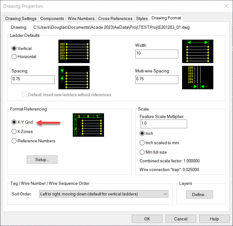
You said the customer will decide the equipment code.  If the code will be the same for all drawings in the project, you could type it into the beginning of the wire number format field. That is what Jim was referring to with XX%S%N, with %N set to X-Y Grid on the Drawing Format tab (see screenshot).  The XX is the equipment code.  Do this in Project Properties and apply to all drawings, to avoid having to add it to each sheet’s Wire Number format.  


If you have a designation that must be different for each drawing, use the Drawing field and add %D to the Wire Number Format.  Replaceable Parameter %D represents the Drawing field for each sheet.  Note that you can add the %D to the Project Properties Wire Number Format field and apply to all drawings, to avoid entering it manually for each drawing.  Most don’t use the Drawing field for Drawing Number/Designation.  Most use a document number and sheet number scheme, so the Drawing field is usually left blank, or used for something else.  For example, I’ve seen it used for scale.  So, using the %D approach, you will type the code for %D into the Drawing Field of each drawing's Drawing Properties.  I've included screenshots showing how to set up for using %D.

Doug McAlexander
Design Engineer/Consultant/Instructor/Mentor
Specializing in AutoCAD Electrical Implementation Support
Phone: (770) 841-8009
www.linkedin.com/in/doug-mcalexander-1a77623

Did you find this post helpful? Feel free to Like this post.
Did your question get successfully answered? Then click on the ACCEPT SOLUTION button.

EESignature

0 Likes
Message 9 of 9

rickstarosto4361
Advocate
Advocate

Forgive me for my ignorance, but as I have mentioned many times before, I am self-teaching on a as time allows basis here no support from department and I am the only one using autocad (mechanical) to do our electrical drawings so I only have this forum.’’


Our projects are set up as 4 installation codes, each having separate drawing numbers be it circuits, term list, cable list, panel outline, component list. So with my beginner project, yes I guess I am using %D drawing number field. I am not sure what and how “a document number_sheet number scheme” works or how to set that up yet.


The customer equipment code at his stage I don’t know how that will be set up but if I work toward multiple codes I should be ok?.

0 Likes