Scissor rig with 2 sliding legs

Scissor rig with 2 sliding legs

jasond240
Enthusiast Enthusiast
3,522 Views
9 Replies
Message 1 of 10

Scissor rig with 2 sliding legs

jasond240
Enthusiast
Enthusiast

I have a simple scissor rig that works using using bones and helpers on a path constraint from this link on the forum.

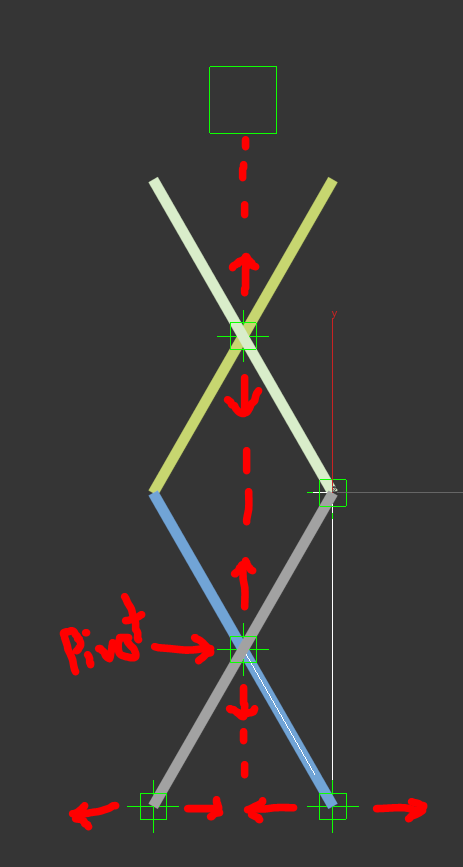
Problem is that this only slides one of the scissor legs at the base. How do I go about sliding both legs away from the midpoint at the base of the stack (see picture below)?


I've tried several bone and IK configurations but can't get it to collapse properly. It has similarities to the recent scissor gate tutorial from @leeminardi but much less complex. Incrementing the stack like in the tutorial is super handy for when you need to add more height to the scissors.


How would I go about adapting these types of scissor rigs to what I'm after?


scissor.PNG


Thanks!

JD

0 Likes
3,523 Views
9 Replies
Replies (9)
Message 2 of 10

leeminardi
Mentor
Mentor

No need for bones or a path constraint.  I would start by rigging one of the "X's" with the action you want. Do you know how to make a simple 4-bar linkage for the "X" using an HI IK SOlver? It's important where you position the pivot points for the objects and to identify which point of the main link will not move and what you want to move to make the scissor open and close. Could you make a print of the mechanism and label the fixed point and the object that will drive the linkage.  After you have the X rigged you can use the technique I outline in my tutorial to drive the other links.  Post a copy of the file and I will get you started.

Lee 

lee.minardi
0 Likes
Message 3 of 10

jasond240
Enthusiast
Enthusiast

Wow, super quick reply! Technically all the pivots in the screenshot will be moving: centre ones up/down, ends up(down)/out(in), nothing is fixed unless I'm missing something. An arbitrary driving object could just be a dummy at the top.


Added a test HIK to compress the X about the centre but the centre moves horizontally as well as vertically in this case, which it shouldn't. The centre of the X can only move vertically while the bottom-most X points should only move horizontally (marked w/arrows below). Am I not creating the HIK using the correct points to create the linkage? 


scissor motion2.PNG

0 Likes
Message 4 of 10

leeminardi
Mentor
Mentor

In the scissor lift shown below point A is considered to be fixed while point B moves back and forth horizontally.  You have set up your scissor linkage with the expectation that the intersection point of the of the "X" (line002 and line003) Point C is the stationary point.  Is this what you really want?  Point C moves up and down as well as side to side.


ScissorLabs.png


It is important when setting up a rig like this that you are aware of the plane of action for the HI IK Solver. I assume your mechanism will use a plane parallel to the YZ plane.  Therefore you should be sure to make the X coordinate the same for all of the pivots referenced by the IK solver in the linkage.  The geometry of the links may have different x coordinates as some links will be in front of others but their pivots will all lie in the desired YZ plane.  


I suggest you:

1. Delete the IK chain.

2. Move the pivot of Line002 to the lower right point (and set it x coordinate).

3. Link Line003 to Line002 (make sure the x coordinate of Line003 is the same as Line002).

4. Link Point003 to Line 003

 (again, check the x coordinate of the point)

5. Select Line002 and then click  Animation, IK SOlver, HI Solver then click Point003.

You can now move Point003 up and down and the first stage of the scissor will work.  When you get that working we can continue with the other links as in my tutorial using expression controllers.

Good luck.


lee.minardi
0 Likes
Message 5 of 10

jasond240
Enthusiast
Enthusiast

Hi Lee,
Your image is correct in that A is pinned for many scissor models however for this particular large scissor lift, both A and B move horizontally on a track. There are some intermediate control arms and hydraulic cylinders that guide their horizontal position and keep point C horizontally constrained. It can only move vertically.


I followed your instructions however it pins A when it should actually be moving.


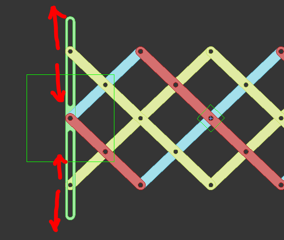
Below is a screenshot of your scissor gate tutorial which partially accomplishes what I'm after. I coloured these segments in yellow. They are sliding in the track as I need to implement.


Capture.PNG


As always, thank you so much for your help in these forums!

JD

0 Likes
Message 6 of 10

leeminardi
Mentor
Mentor

I took a different approach for your scissor mechanism.  Rather than using an IK solver, a single simple trig statement is used to control the angle of the scissor links.

I created a dummy named DummyControl.  It's X position relative to the Base Dummy is used to define the extension of the mechanism. It has locks on its Y and Z position so it can only move in the x direction relative to DummyBase. Link001 (red link) has a Expression Controller for its position and another one for its rotation about the z axis.  The rotation of Link001 is simply  = acos((distance of dummy control from base) / 200) where 200 is the length from the end of the link to the center.

Additional links can be created by cloning links 3 and 4 then editing the multiple of dumpos.


Let me know if you have any questions.  I gotta run.

scis1.JPG


lee.minardi
0 Likes
Message 7 of 10

jasond240
Enthusiast
Enthusiast
Hi Lee,
Very interesting approach! At what rotation of the links do you assign the rotation expression controller? When I try to re-create your example, the links do not retain their initial rotation when you evaluate the expression. This disconnects them from the other links/base.

Also, how would I add a dummy at the top of the stack to link the scissor platform to? I thought of an attachment constraint to the top of the right-most side of the link in the example but that doesn't seem particularly appropriate here.

Many thanks!
JD
0 Likes
Message 8 of 10

leeminardi
Mentor
Mentor

JD,

Here are a few tips and suggestions.

  1. I started with two links in a horizontal orientation made from an outline that was extruded. The red link has its pivot on the bottom while the blue link has its pivot on top
  2. Things are much easier if a principal axis is in the direction of the link. For me the  local x axis of the links point in the long direction of the link.  I think you started with lines with a renderable thickness with badly oriented pivots.
  3. I link everything to a base dummy so that the final mechanism can be positioned and rotate anywhere in 3D.
  4. To answer your question, it doesn’t matter “at what rotation of the link “ you assign the expression controller. I assigned the position expression controller first to Link001. After clicking evaluate it should be centered on DummyControl. If it is not make sure it is also linked to DummyBase. I then created an expression controller (Float Expression) for the Z rotation of Link001.
  5. “…how would I add a dummy at the top of the stack to link the scissor platform to?” I would add an expression controller to the “platform” dummy that uses the position of DummyControl relative to DummyBase. For example, Let’s assume there are three “X’s” to the mechanism, the position of DummyPlatform is 6 times the distance from DummyBase to DummyControl.
  6. Note you have a decision here whether you want to work with a distance (a scalar) or a vector. If we decide to use a scalar distance for positioning DummyPlatform then we could use a Float Expression controller for its X position. Since DummyPlatfrom is linked to DummyBase its X the position value we get in the expression controller is already relative to DummyBase and the expression for the X position of DummyPlatform is:
       6 * dControl    
    where dControl ha been assigned the x value of DummyControl.
    scis2.JPG


    Using a scalar to position DummyPlatform does not address the need to also address its Y and Z coordinates. You could manually adjust the Y and Z values and then lock them (via Hierarchy, Link Info).
  7. Instead of using a scalar distance you could use a vector. Here you would assign a Position Expression to the Position   of DummyPlatform. The expression would be the same but the result is a vector since the variable dControl has been defined as a vector (the 3D location of DummyControl relative to DummyBase).  No need to worry about the Y and Z coordinates if they are controlled by DummyControl.scis3.JPG


I hope this explanation isn't too long winded but I think there is a certain beauty with how Max let's you control object position and rotation and I'm glad to share what I have learned.

Let mw know if you have any more questions.

Lee

lee.minardi
0 Likes
Message 9 of 10

jasond240
Enthusiast
Enthusiast

I ended up using a vector to place the top dummy, don't know why I didn't think of that since its so similar to when you add another pair of links to the scissors.


Here's the kicker,

I started with two links in a horizontal orientation made from an outline that was extruded. The red link has its pivot on the bottom while the blue link has its pivot on top
  1. Things are much easier if a principal axis is in the direction of the link. For me the  local x axis of the links point in the long direction of the link.  I think you started with lines with a renderable thickness with badly oriented pivots.

We are working from engineering models where the scissors are already in a fully elevated position. This means that we cannot rotate the links to a horizontal orientation prior to setting up the expression controller as you've done in your example. If we did, it would become very difficult to realign the stack with all the pins, etc. as the rotation is essentially arbitrary. The example I posted was just a quick mock-up. I tried rotating DummyControl to match the initial link rotation but this did not work. I think we need something similar to orientation constraints 'keep initial offset'.


Thanks so much!

JD

0 Likes
Message 10 of 10

leeminardi
Mentor
Mentor

I think you can just orient the pivot of the links so that a principal local axis points in the direction of the link then use the approach I outlined.

I sometimes found it difficult with Max functions to orient an object's pivot the way I wanted so last year I wrote a Maxscript to help me.  I just modified it to work with two user specified points which I think would be helpful.  Just select one of your links and  execute the script  and follow the prompts to identify two points.  The script will reorient the local Z axis of the object so that it points in the direction of the two points.  Use snaps to access the reference points of the link.

After using the script you can use the z axis (rather than the x axis I used for the scissor) or rotate the pivot by 90° about Y to have the X axis point in the direction of the link.


-- relocates the pivot of a selected object to the first 
-- point specified by the user and with its Z axis point
-- towrds the second point specified.
-- L. Minardi 1/31/2019 v1
--
for spl in selection do (
s=1
e1 = pickPoint prompt:"\nPick new pivot location" snap:#3D
e2 = pickPoint prompt:"\nPick point on new Z axis for pivot" snap:#3D
v = e2-e1 -- vector from vertex 1 to 2
vlen = length(v)
vu = v/vlen -- unit vector
m = spl.transform -- object matrix
ftm = translate (matrixfromnormal vu) e1
itm = ftm*(inverse m)
spl.transform = ftm
spl.objectOffsetPos *= inverse itm
spl.objectOffsetRot *= inverse itm.rotation
spl.transform
)

I am traveling next week and will not have access to Max and limited computer access.  If you would like me to check out your rigging feel free to post a file today of just the links you need to rig and I will take a look at it.  Please note which version of Max you are using.


lee.minardi
0 Likes