Community
- Forums Home
- >
- Fusion Community
- >
- Design, Validate & Document forum
- >
- Re: Importing SVG files as sketches
Fusion Design, Validate & Document
Stuck on a workflow? Have a tricky question about a Fusion (formerly Fusion 360) feature? Share your project, tips and tricks, ask questions, and get advice from the community.
Turn on suggestions
Auto-suggest helps you quickly narrow down your search results by suggesting possible matches as you type.
Reply
Topic Options
- Subscribe to RSS Feed
- Mark Topic as New
- Mark Topic as Read
- Float this Topic for Current User
- Bookmark
- Subscribe
- Printer Friendly Page
Message 1 of 24
Anonymous
57253 Views, 23 Replies
10-19-2013
01:28 AM
- Mark as New
- Bookmark
- Subscribe
- Mute
- Subscribe to RSS Feed
- Permalink
- Report
10-19-2013
01:28 AM
This was apparently implemented in October, (the ability to import SVG files)...
Is there any instructions available as to how to do this?
If this allows the use of SVG files for sketches (so I can import designs from Illustrator for incorporation and creation of 3D items) that would be awesome.
But it just isn't clear how to do this.
Thanks for any help
Solved! Go to Solution.
Solved by paul.clauss. Go to Solution.
23 REPLIES 23
Message 2 of 24
10-19-2013
01:43 AM
- Mark as New
- Bookmark
- Subscribe
- Mute
- Subscribe to RSS Feed
- Permalink
- Report
10-19-2013
01:43 AM
i already answered your question in the idea section.
Just choose "import svg" from the sketch menu when inside a sketch and select your svg file. If it's a closed loop it gets imported well and you can for example extrude it or do anything else with it you would do with other sketches.
Just choose "import svg" from the sketch menu when inside a sketch and select your svg file. If it's a closed loop it gets imported well and you can for example extrude it or do anything else with it you would do with other sketches.
---
Frank / @helmi
Established 1974. Internet addicted since 1994. Collector of Kudos.
Frank / @helmi
Established 1974. Internet addicted since 1994. Collector of Kudos.
Message 3 of 24
10-19-2013
02:27 AM
- Mark as New
- Bookmark
- Subscribe
- Mute
- Subscribe to RSS Feed
- Permalink
- Report
10-19-2013
02:27 AM
Ah, thanks.
This is a somewhat bad UI choice as the menu item appears and disappears based on selection. Instead it should enable or disable.
But this makes a huge improvement for me as there are some things that can be drawn in Illustrator much quicker than in sketch mode and then moved over (for example, the use of auto trace). And it gives wonderful text support!
Message 4 of 24
10-19-2013
02:58 AM
- Mark as New
- Bookmark
- Subscribe
- Mute
- Subscribe to RSS Feed
- Permalink
- Report
10-19-2013
02:58 AM
you're right on both parts - horrible UI decision but that still could be changed i think, and also you're right that this is a greatly needed feature. That's why we posted that in the ideas section.
---
Frank / @helmi
Established 1974. Internet addicted since 1994. Collector of Kudos.
Frank / @helmi
Established 1974. Internet addicted since 1994. Collector of Kudos.
Message 5 of 24
10-19-2013
09:24 PM
- Mark as New
- Bookmark
- Subscribe
- Mute
- Subscribe to RSS Feed
- Permalink
- Report
10-19-2013
09:24 PM
Well, horrible UI decision might be a little strong.
But it does go against the Apple Human Interface Guidelines (granted, not my book so I don?t read it that often, but I recall that was the rule - I can ask)
I?m not sure how I feel about the new UI, it?s not as easy to select the items.
But this SVG feature is awesome.
But it does go against the Apple Human Interface Guidelines (granted, not my book so I don?t read it that often, but I recall that was the rule - I can ask)
I?m not sure how I feel about the new UI, it?s not as easy to select the items.
But this SVG feature is awesome.
Message 6 of 24
10-19-2013
10:49 PM
- Mark as New
- Bookmark
- Subscribe
- Mute
- Subscribe to RSS Feed
- Permalink
- Report
10-19-2013
10:49 PM
not horrible UI of course - i like the new UI. But the decision to hide a menu item just because it's inactive next to others from the same "group" that are not hidden at the same time - this is a horrible decision in my opinion.
---
Frank / @helmi
Established 1974. Internet addicted since 1994. Collector of Kudos.
Frank / @helmi
Established 1974. Internet addicted since 1994. Collector of Kudos.
Message 7 of 24
10-25-2013
08:24 AM
- Mark as New
- Bookmark
- Subscribe
- Mute
- Subscribe to RSS Feed
- Permalink
- Report
10-25-2013
08:24 AM
I agree that the SVG should be visible and selectable outside the sketch environment. Upon selection the user should be prompted for a plane to define where the SVG will be placed. It should probably provide scaling and positioning handles by default. What do you think? I will create an improvement.
Message 8 of 24
10-27-2013
04:52 AM
- Mark as New
- Bookmark
- Subscribe
- Mute
- Subscribe to RSS Feed
- Permalink
- Report
10-27-2013
04:52 AM
I think those would be good improvements.
Outside of a sketch I can see (if it made a sketch).
I'm wondering if it's possible to wrap one on a curved surface.. that would be useful as well.
Scott
Outside of a sketch I can see (if it made a sketch).
I'm wondering if it's possible to wrap one on a curved surface.. that would be useful as well.
Scott
Message 9 of 24
11-12-2013
04:36 PM
- Mark as New
- Bookmark
- Subscribe
- Mute
- Subscribe to RSS Feed
- Permalink
- Report
11-12-2013
04:36 PM
I'm having a bit of trouble with this - My closed-loop SVG is importing, but it's not recognized as a closed loop and therefore is really difficult to work with. Anyone know why a SVG would seem closed in Illustrator but open in F360?
Message 10 of 24
11-12-2013
05:59 PM
- Mark as New
- Bookmark
- Subscribe
- Mute
- Subscribe to RSS Feed
- Permalink
- Report
11-12-2013
05:59 PM
We are running into this from time to time. Can you email me the SVG file at andrew.sears@autodesk.com?
The translation is creating an small opening sometimes. Add a sketch line at the halfway point. This will tell you what side(s) have the opening.
Let me know if you need any help and I will show you what I have done with more detail.
Thanks,
Andy
Message 11 of 24
02-18-2014
12:23 PM
- Mark as New
- Bookmark
- Subscribe
- Mute
- Subscribe to RSS Feed
- Permalink
- Report
02-18-2014
12:23 PM
Is closed loop handling in imported SVG still actively in development / known bugs?
I have an SVG import that has generally good closed loop detection except for one inner loop.
The odd thing is if I then select the line components of that loop, copy them, and paste them in a new sketch the loop is closed.
I can provide sources if it helps.
Message 12 of 24
02-18-2014
12:40 PM
- Mark as New
- Bookmark
- Subscribe
- Mute
- Subscribe to RSS Feed
- Permalink
- Report
02-18-2014
12:40 PM
Here is a screen capture.
The brown region is the oddity. I dont know why it is brown, but this is indicative of the issue.
The outer loop in light grey extrudes nicely.
The innerloop which should have the brown region as a void, highlights the brown region in the selection set as well, and extrudes it all.
I can copy the outline line components of the brown region, paste into another sketch and extrude that fine, but it will not subtract from the other solid body I have extruded.
Indeed the region that should be a void has other odd render issues so there is something very wrong with this brown region. See second image, where I show the extruded part and the odd rendering in this region.


Message 13 of 24
02-18-2014
01:40 PM
- Mark as New
- Bookmark
- Subscribe
- Mute
- Subscribe to RSS Feed
- Permalink
- Report
02-18-2014
01:40 PM
Further to this the oddly rendered region is of zero thickness, I can slice with an offset plane and get rid of this surface anomylee, though I have to do so on the top and bottom of the solid!
Message 14 of 24
10-16-2014
10:10 AM
- Mark as New
- Bookmark
- Subscribe
- Mute
- Subscribe to RSS Feed
- Permalink
- Report
10-16-2014
10:10 AM
Hello Andrew,
I am having the same issues, and I wonder if you could explain a little bit more the drawing of a line, so we can see the inconsistencies.
Thank you
Message 15 of 24
11-14-2014
02:37 PM
- Mark as New
- Bookmark
- Subscribe
- Mute
- Subscribe to RSS Feed
- Permalink
- Report
11-14-2014
02:37 PM
HI,
I know there has not been activity on this thread for a while but if this is still a concern for you and seeing other files exibiting the same behaviour, can you please send the svg file to raj.kumar.ilanchelian@autodesk.com?
Rajkumar Ilanchelian
Autodesk Fusion
Join Fusion Insider
Message 16 of 24
11-17-2014
09:56 AM
- Mark as New
- Bookmark
- Subscribe
- Mute
- Subscribe to RSS Feed
- Permalink
- Report
11-17-2014
09:56 AM
To answer the original post:
Insert SVG is a full time tool that is available in the Insert menu now.

Phil Eichmiller
Software Engineer
Quality Assurance
Autodesk, Inc.
Message 17 of 24
10-13-2016
02:51 PM
- Mark as New
- Bookmark
- Subscribe
- Mute
- Subscribe to RSS Feed
- Permalink
- Report
10-13-2016
02:51 PM
Hi All!
I noticed this page is still getting a lot of traffic and has not been updated in some time, so I wanted to give a brief walk-through on how to import SVG Files as Sketches in Fusion 360.
SVG files can provide a variety of advantages over other formats, particularly in web design where scalability can be extremely important. But what if you have a SVG –formatted logo from your graphic designer that you want to manufacture into a 3-dimensional form?
Luckily, Fusion 360 is capable of importing SVG files to sketches! This allows product designers and manufacturers to create 3D objects using 2 dimensional designs, such as logos.
To import an SVG file to a sketch in Fusion 360, simply follow this procedure:
- From the ribbon in the Model Workspace, Select Insert SVG

SVG files must be imported with this method instead of uploaded as Fusion designs because SVG files can only be imported to active sketches.
- Selecting the Insert SVG option will prompt you to select the plane you want to sketch on

Select the plane you want to insert the SVG file in the same way as if you were selecting a plane to sketch on.
- After selecting the plane on which to insert the SVG, the manipulator will allow you to move and resize the SVG sketch.

The manipulator handles will allow you to move, rotate, and scale the SVG image on the active sketch plane.
- Once the sketch is in the correct location and scaled correctly, select “OK” in the Insert SVG dialogue box.

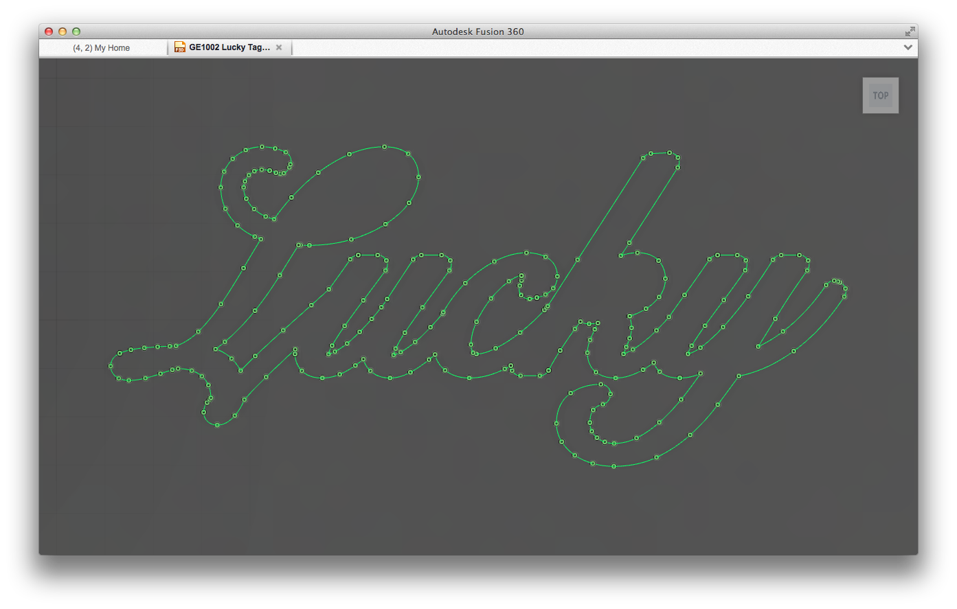
This finishes inserting the SVG file as an active sketch. As you can see, Fusion 360 recognizes closed contours in the same way it would with any sketch.
- Now you can create 3D geometry from your imported SVG file in the same way as you can with sketch geometry native to Fusion 360.

This allows you to create bodies and components using any of the methods available in Fusion 360 from your imported SVG sketch. The part is now nearly ready for 3D printing or the CAM workspace!
I have also attached a screencast illustrating this process below. Hopefully this helps everyone gain a better understanding of how to import SVG files as sketches in Fusion 360!
Message 18 of 24
02-08-2017
03:10 PM
- Mark as New
- Bookmark
- Subscribe
- Mute
- Subscribe to RSS Feed
- Permalink
- Report
02-08-2017
03:10 PM
I am getting a similar issue with my drawing. Were you able to solve the problem?
Message 19 of 24
Anonymous
in reply to:
Anonymous
07-31-2017
02:06 PM
- Mark as New
- Bookmark
- Subscribe
- Mute
- Subscribe to RSS Feed
- Permalink
- Report
07-31-2017
02:06 PM
I am too having svg import issues. I'm a new user so just trying to figure out why too.
File looks fine in illustrator. The paths on one side warp out strangely when inserted into fusion 🙈
Message 20 of 24
08-16-2020
01:02 AM
- Mark as New
- Bookmark
- Subscribe
- Mute
- Subscribe to RSS Feed
- Permalink
- Report
08-16-2020
01:02 AM
Thanks for your guide, it makes working with Fusion a lot easier. I use to import .svg files and it worked good. But now I have a file that wont work. I get an error message that the .svg file does not contain information or does not support the information. Where is the problem?
Reply
Topic Options
- Subscribe to RSS Feed
- Mark Topic as New
- Mark Topic as Read
- Float this Topic for Current User
- Bookmark
- Subscribe
- Printer Friendly Page
Forums Links
Can't find what you're looking for? Ask the community or share your knowledge.
Post to forums
