Community
Moldflow Insight Forum
Welcome to Autodesk’s Moldflow Insight Forums. Share your knowledge, ask questions, and explore popular Moldflow Insight topics.
Turn on suggestions
Auto-suggest helps you quickly narrow down your search results by suggesting possible matches as you type.
Reply
Topic Options
- Subscribe to RSS Feed
- Mark Topic as New
- Mark Topic as Read
- Float this Topic for Current User
- Bookmark
- Subscribe
- Printer Friendly Page
Message 1 of 11
Anonymous
1929 Views, 10 Replies
06-01-2011
07:46 AM
- Mark as New
- Bookmark
- Subscribe
- Mute
- Subscribe to RSS Feed
- Permalink
- Report
06-01-2011
07:46 AM
modeling bubbler
hi every one ,
for my anlysis i need a bubbler cooling system , i have draft that with the help of the instruction in the help (modeling bubbler )
but every time after the mesh my bubbler have intersetion , i have try the the mesh repair Winzar to corect the intersection , but nothing change .
so if same one can help me please.
thank u so mutch
samica 🙂
10 REPLIES 10
Message 2 of 11
Anonymous
in reply to:
Anonymous
06-02-2011
04:30 AM
- Mark as New
- Bookmark
- Subscribe
- Mute
- Subscribe to RSS Feed
- Permalink
- Report
06-02-2011
04:30 AM
Try running the analysis. The intersection might be OK (as long as the part mesh has no intersections).
It may be just how the bubblers are modeled. Did you have overlapping curves for bubblers (which is acceptable). Even if no overlapping curves it may still show intersections. Just make sure that the bubblers dont intersect with the part mesh.
Message 3 of 11
Anonymous
in reply to:
Anonymous
06-02-2011
05:18 AM
- Mark as New
- Bookmark
- Subscribe
- Mute
- Subscribe to RSS Feed
- Permalink
- Report
06-02-2011
05:18 AM
Thanks for reply
the part mesh have not intersection , the intersection are in the bubbler , i have run the analysis and she was succesful with 7 warrning, the result of the the warp is olso get better , but i dont now if thos intersection dont make the anlysis not good , and how can i solve those warning .
thanks so much ( and sorry for my bad english )
samica
Message 4 of 11
Anonymous
in reply to:
Anonymous
06-10-2011
07:07 AM
- Mark as New
- Bookmark
- Subscribe
- Mute
- Subscribe to RSS Feed
- Permalink
- Report
06-10-2011
07:07 AM
Bubbles are always giving error warnings .... ignor them in most cases.
I suggest you make a "dummy" file with a "bubbler" , anoterh with a thermal pin , etc. in a "tooling" master project.
Then just "add" the geomtry to the part you are evaluating and modify ( length usually )
Hope that makes sense
Message 5 of 11
06-11-2011
04:02 AM
- Mark as New
- Bookmark
- Subscribe
- Mute
- Subscribe to RSS Feed
- Permalink
- Report
06-11-2011
04:02 AM
The troubles of overlapping are normal with bubblers.
You can see where they occur using the tool : mesh / diagnostic / overlaping.
For cooling analysis, the main problem is when the calculation is unable to converg.
Take care about these warnings in the summary.
To solve them, the size of channels mesh have to be clearly bigger than the one of the part.
(I believe 2.5 times. Control this in the Help)
But, it is often not possible all along the channels.
Signature: "Maybe Moldflow does not work properly, but the real world neither" my son...6 years old 😉
Message 6 of 11
06-14-2011
07:15 AM
- Mark as New
- Bookmark
- Subscribe
- Mute
- Subscribe to RSS Feed
- Permalink
- Report
06-14-2011
07:15 AM
The picture joined shows an example of the overlapping diagnostic you get with bubblers.
As I said before, this is normal and do not cause cooling analysis errors.
Signature: "Maybe Moldflow does not work properly, but the real world neither" my son...6 years old 😉
Message 7 of 11
Anonymous
in reply to:
Anonymous
06-15-2011
02:03 AM
- Mark as New
- Bookmark
- Subscribe
- Mute
- Subscribe to RSS Feed
- Permalink
- Report
06-15-2011
02:03 AM
Firstly, I confirm that the intersection are normal with bubblers, baffles and in general with beam elements, but this condtion has not negative effects on the analysis.
I have now a question for you on the modeling of the bubblers:
looking the help is clear that when you draw a baffle the final node must 1/2 diam. shorter than the real hole, but it's not specified for the bubbler. Actually I put the node at the same level of the extremity of the hole, but I'm not sure about it.
Has someone verified this thing ?
Thanks to all
Alessandro
Message 8 of 11
06-15-2011
04:07 AM
- Mark as New
- Bookmark
- Subscribe
- Mute
- Subscribe to RSS Feed
- Permalink
- Report
06-15-2011
04:07 AM
For both Baffles and Bubblers, the top node must be half the diameter below the drilled hole. This is because the solver will add half the diameter to the node position during the cool analysis.
As for the intersections, this is normal in a cooling circuit. It is important that the global edge length of your cooling channels is set to be 2 to 3 times the diameter of the cooling channel. If the cooling line diameters are significantly different, the global edge length should be changed for the various diameters.
If my post answers your question, please click the "Accept as Solution" button. This helps everyone find answers more quickly!

Paul Larter
Paul Larter
Message 9 of 11
Anonymous
in reply to:
Anonymous
01-12-2013
09:31 AM
- Mark as New
- Bookmark
- Subscribe
- Mute
- Subscribe to RSS Feed
- Permalink
- Report
01-12-2013
09:31 AM
Hello!
I would like to ask a question about modelling a baffle. I understand the meshing method and the two overlapping beam element. My question is about the diameter of the to beam elements.
If i have a baffle than I should use the same diameter for both of the beam elements which are the outer diameter of my baffle? Please see attached picture.
If I use a bubbler, than I should use different diameters, one for the inner pipe of the bubbler and one for the outer pipe?
Thanks!
BR
András
Message 10 of 11
Anonymous
in reply to:
Anonymous
01-13-2013
04:38 AM
- Mark as New
- Bookmark
- Subscribe
- Mute
- Subscribe to RSS Feed
- Permalink
- Report
01-13-2013
04:38 AM
Hello!
I also have another question about the last node of the baffle.
It is written here eariler:
"For both Baffles and Bubblers, the top node must be half the diameter below the drilled hole. This is because the solver will add half the diameter to the node position during the cool analysis."
But is it depends on the coordinate system?
Please see the attached picture. In my opinion the blue heat zone should be higher and for me it looks like that the solver put this half diameter to the wrong direction. Is it possible? Please check the coordinate system in the left bottom corner.
BR,
András
Message 11 of 11
01-15-2013
01:56 AM
- Mark as New
- Bookmark
- Subscribe
- Mute
- Subscribe to RSS Feed
- Permalink
- Report
01-15-2013
01:56 AM
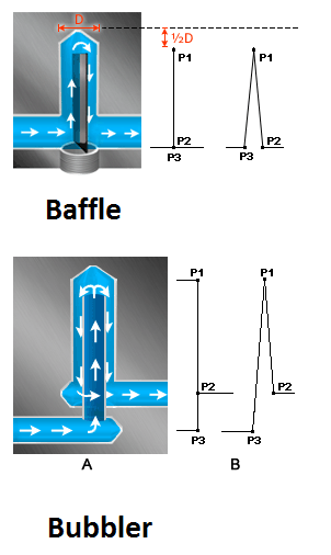
refer image for details.
1. intersetion will be allowed.
2. But there should not be intersection in centre line of channel.
3. apply Channel heat transfer effectiveness (HTE) is 0.5 for baffle line, Channel heat transfer effectiveness (HTE) is zero for bubbler inlet pipe and Channel heat transfer effectiveness (HTE) is 1 for outer pipe of bubbler.
4. 1/2 D , distance is for baffle and not for bubbler
Madhukeshwar Talwar

FORD MOTORS PRIVATE LIMITED, Chennai
mail: madhukeshwart@gmail.com
09600060862
======================================
Please use . Accept as Solution and Give Kudos as appropriate to further enhance these forums. Thank you! .....
FORD MOTORS PRIVATE LIMITED, Chennai
mail: madhukeshwart@gmail.com
09600060862
======================================
Please use . Accept as Solution and Give Kudos as appropriate to further enhance these forums. Thank you! .....
Reply
Topic Options
- Subscribe to RSS Feed
- Mark Topic as New
- Mark Topic as Read
- Float this Topic for Current User
- Bookmark
- Subscribe
- Printer Friendly Page
Forums Links
Can't find what you're looking for? Ask the community or share your knowledge.
Post to forums
