Community
- Forums Home
- >
- Moldflow insight Community
- >
- Moldflow Insight Forum
- >
- Re: Imbalance in Pressure Vs Switchover
Moldflow Insight Forum
Welcome to Autodesk’s Moldflow Insight Forums. Share your knowledge, ask questions, and explore popular Moldflow Insight topics.
Turn on suggestions
Auto-suggest helps you quickly narrow down your search results by suggesting possible matches as you type.
Reply
Topic Options
- Subscribe to RSS Feed
- Mark Topic as New
- Mark Topic as Read
- Float this Topic for Current User
- Bookmark
- Subscribe
- Printer Friendly Page
Message 1 of 10
Anonymous
845 Views, 9 Replies
03-03-2012
11:12 AM
- Mark as New
- Bookmark
- Subscribe
- Mute
- Subscribe to RSS Feed
- Permalink
- Report
03-03-2012
11:12 AM
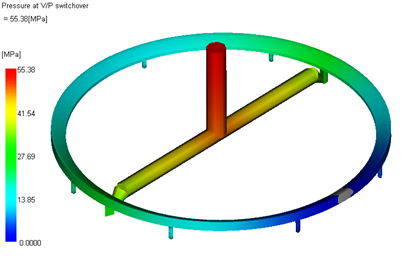
Imbalance in Pressure Vs Switchover
Hi All
This is a symmetric component. Why is there an imbalance in Pressure Vs Switchover?
Thanks in Advance
Regards
Vinod Tiwari
Hyderabad
India
9 REPLIES 9
Message 2 of 10
Anonymous
in reply to:
Anonymous
03-03-2012
04:10 PM
- Mark as New
- Bookmark
- Subscribe
- Mute
- Subscribe to RSS Feed
- Permalink
- Report
03-03-2012
04:10 PM
There is probably some asymmetry in the mesh, causing little asymmetry of fill.
Sometimes violations of symmetry of fill can be real. Usually it happens if the frozen layer is >30% or significant shear heating is present: minuscle drop in flow in one branch (due to machining tolerances, e.g.) causing some cooling of this branch, causing higher resistance, causing additional drop in flow, causing additional cooling, etc.... As with a ball on a top of a symmetrical hill we don't know which way it will roll down but we know that it will fall, for the unstable flows simulation can predict a violation in symmetry but cannot predict the direction.
Message 4 of 10
Anonymous
in reply to:
Anonymous
03-05-2012
04:11 PM
- Mark as New
- Bookmark
- Subscribe
- Mute
- Subscribe to RSS Feed
- Permalink
- Report
03-05-2012
04:11 PM
Hi,
I also want to ask that my pressure profile at switchover has changed from uniform to non-uniform with increase in only the starting ram position, keeping all other parameters constant, what could be the possible reasons behind this?
Regards,
Simransingh
Message 5 of 10
Anonymous
in reply to:
Anonymous
03-05-2012
09:24 PM
- Mark as New
- Bookmark
- Subscribe
- Mute
- Subscribe to RSS Feed
- Permalink
- Report
03-05-2012
09:24 PM
AMI takes into account compressibility of melt in the barrel, changing the starting position of RAM we change this effect. Thus, changing starting position of RAM affects flow and may trigger a flow instability. So it might be real although I would not bet my life that this is a prediction of a real phenomena rather than some numerical artifact.
Message 7 of 10
03-09-2012
02:32 AM
- Mark as New
- Bookmark
- Subscribe
- Mute
- Subscribe to RSS Feed
- Permalink
- Report
03-09-2012
02:32 AM
Vinod,
If it is fusion mesh/DD mesh / 3d mesh,
Many times it happens due to assymetry of mesh only.
first do only half mesh and then reflect it and connect it.Then run the analysis. it works fine
If not solved send to sdy file me. I will try to help you
Regards,
Madhukeshwar Talwar
Madhukeshwar Talwar

FORD MOTORS PRIVATE LIMITED, Chennai
mail: madhukeshwart@gmail.com
09600060862
======================================
Please use . Accept as Solution and Give Kudos as appropriate to further enhance these forums. Thank you! .....
FORD MOTORS PRIVATE LIMITED, Chennai
mail: madhukeshwart@gmail.com
09600060862
======================================
Please use . Accept as Solution and Give Kudos as appropriate to further enhance these forums. Thank you! .....
Message 9 of 10
03-12-2012
08:29 AM
- Mark as New
- Bookmark
- Subscribe
- Mute
- Subscribe to RSS Feed
- Permalink
- Report
03-12-2012
08:29 AM
A few last pointers:
First of all, I 100% agree with Alext that an imbalance of imbalance can happen in reality. Slight imbalances can in certain scenarios get progressively worse. This is one of the unfortunate things in injection molding.
When you see this happen in the software, it should be a red flag for you; there can be an issue.
It's worth looking at this a bit closer though; if the mesh is relatively coarse, the initial numerical imbalance that triggers the imbalance can have to do with the flow front scheme. For Midplane and Dual Domain you can find this in the solver options, in the 'convergence' tab, under the name of 'nodal growth mechanism'. This parameter dictates how many nodes are filled every time step. The default setting 'multiple' fills multiple nodes at every time step. The underlying algorithm is pretty sophisticated, but in principle it's possible that by 'chance' during one time step, one side fills 5 nodes and the other side 3. This is effectively an imbalance, but under most conditions this slight imbalance will not have severe consequences, and the solver would likely correct this imbalance in the next step. Under some exceptional cases however this initial imbalance is just severe enough to trigger an imbalance in the sheer rates and consequently in the shear heating, causing a viscosity imbalance and a real imbalance in the next step.
To get a better handle on this, you can choose to set the nodal growth scheme to 'single' (so every time step one node gets filled). This can reduce the initial 'trigger imbalance'. As a side effect, you will see the solver become much slower now.
Hanno
Hanno van Raalte,
Product Manager - Injection Molding & Moldflow products
Product Manager - Injection Molding & Moldflow products
Message 10 of 10
07-17-2012
05:47 AM
- Mark as New
- Bookmark
- Subscribe
- Mute
- Subscribe to RSS Feed
- Permalink
- Report
07-17-2012
05:47 AM
Is there any similar option in 3d mesh?
Madhukeshwar Talwar
FORD MOTORS PRIVATE LIMITED, Chennai
mail: madhukeshwart@gmail.com
09600060862
======================================
Please use . Accept as Solution and Give Kudos as appropriate to further enhance these forums. Thank you! .....
FORD MOTORS PRIVATE LIMITED, Chennai
mail: madhukeshwart@gmail.com
09600060862
======================================
Please use . Accept as Solution and Give Kudos as appropriate to further enhance these forums. Thank you! .....
Reply
Topic Options
- Subscribe to RSS Feed
- Mark Topic as New
- Mark Topic as Read
- Float this Topic for Current User
- Bookmark
- Subscribe
- Printer Friendly Page
