Community
Moldflow Insight Forum
Welcome to Autodesk’s Moldflow Insight Forums. Share your knowledge, ask questions, and explore popular Moldflow Insight topics.
Turn on suggestions
Auto-suggest helps you quickly narrow down your search results by suggesting possible matches as you type.
Reply
Topic Options
- Subscribe to RSS Feed
- Mark Topic as New
- Mark Topic as Read
- Float this Topic for Current User
- Bookmark
- Subscribe
- Printer Friendly Page
Message 1 of 11
10-09-2013
02:13 AM
- Mark as New
- Bookmark
- Subscribe
- Mute
- Subscribe to RSS Feed
- Permalink
- Report
10-09-2013
02:13 AM
Ear Flow
I’m disappointed by a ‘bad’ Moldflow filling result. You can see briefly attached the behavior of the physical flow and the simulation.
Today there is a weld line which was not detected by Moldflow.
I tried to remesh the tetras along the edge of the component but the result is not better.
It’s dangerous because I can’t explain to my colleagues why we can’t trust the software only for this case. I hope that they will not think that is a generality.
What is your feeling about this topic?
PS : It's an Outer Lens Component for rear lamp product injected by PMMA 8N
10 REPLIES 10
Message 2 of 11
10-09-2013
10:40 PM
- Mark as New
- Bookmark
- Subscribe
- Mute
- Subscribe to RSS Feed
- Permalink
- Report
Message 3 of 11
10-10-2013
12:07 AM
- Mark as New
- Bookmark
- Subscribe
- Mute
- Subscribe to RSS Feed
- Permalink
- Report
10-10-2013
12:07 AM
Unfortunatly it's not possible to upload the part.
But the observation is very simple. There is a weld line which is not intented by Moldflow because the flow front behavior is not the same that the physical process. The velocity is higher along the edge of the part.
Message 4 of 11
10-10-2013
06:39 AM
- Mark as New
- Bookmark
- Subscribe
- Mute
- Subscribe to RSS Feed
- Permalink
- Report
10-10-2013
06:39 AM
I would suggest looking at the mesh in that area. If it's dual-domain, make sure the thickness is correct to show the thicker edge. Not matter what the mesh type is, make sure there are enough elements along the edge to pick up the flow/weld line. (ie, if your mesh size is 1", and the flow leader along the edge is only 1/2", then it won't pick up the flow difference)
You could always try turning inertia effects on. Sometimes this helps. But it makes it tricky when you need to simulate things correctly in the first place, not after the fact.
Tim
Message 5 of 11
10-10-2013
06:53 AM
- Mark as New
- Bookmark
- Subscribe
- Mute
- Subscribe to RSS Feed
- Permalink
- Report
10-10-2013
06:53 AM
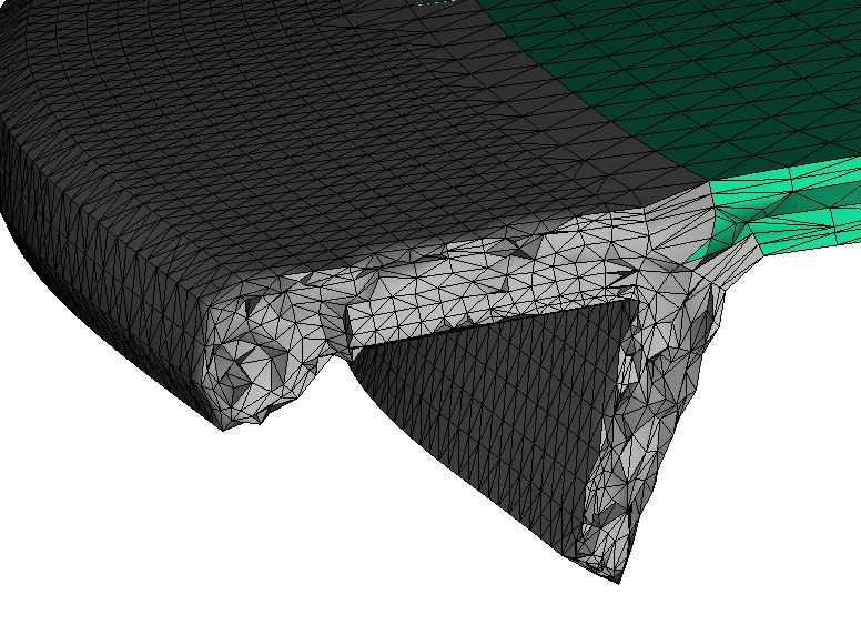
Thanks for your advices Tim,
This simulation was done by 3D model. I remeshed localy the edge to 10 elements (see the picture attached) and a ratio close to 1 but there was no effect on result.
Concerning the inertia effect I already tested it but I guess that it's not really significative for a thin part (2.5 mm). But I can launch one for test.
François
Message 6 of 11
10-10-2013
07:05 AM
- Mark as New
- Bookmark
- Subscribe
- Mute
- Subscribe to RSS Feed
- Permalink
- Report
10-10-2013
07:05 AM
Hmm. Your mesh looks more than adequate to pick up any flow differences. Again, you could try inertia, but I agree with you that it typically doesn't help unless your fill speed is really fast.
Best of luck.
Message 7 of 11
10-15-2013
12:21 PM
- Mark as New
- Bookmark
- Subscribe
- Mute
- Subscribe to RSS Feed
- Permalink
- Report
10-15-2013
12:21 PM
Hello,
its complicated without seeing the whole mesh, but sometimes it can be usefull to mesh 3d with 12 and more layer. And it could be better in your case to mesh the whole part with finer mesh density. What moldflow version do you use?
What quality is your material file. Gold?
if you send me the cad file by peronal mail, iI would test it for you. Should be fast enaough my maschine. 2 processors 96GB.
Philipp
Message 8 of 11
10-16-2013
08:11 AM
- Mark as New
- Bookmark
- Subscribe
- Mute
- Subscribe to RSS Feed
- Permalink
- Report
10-16-2013
08:11 AM
Hi Francois,
I need a little bit more information flow to my ear because you are not able to publish the model itself.
- What is the actual thickness ratio in the model - flow leader outside, thickness in the center?
- How far is the distance of the gate location from the problem area?
- Which PMMA you are using from the Moldflow database?
- Filling time/melt temperature and mold temperature?
This inputs can help me to capture the problem conditions more then yet and brings us hopefully to an helpful answer.
br, Anton
Message 9 of 11
10-17-2013
04:16 AM
- Mark as New
- Bookmark
- Subscribe
- Mute
- Subscribe to RSS Feed
- Permalink
- Report
10-17-2013
04:16 AM
Hi Francois,
It's the first time I see this kind of bad flow results.
It seems that your study doesn't considers cooling lines. What I suggest is checking the cooling parameters and temperature distribution during the trial. In fact the mold temperature may be not so uniform, this could explain such big difference from moldflow study.
Message 10 of 11
10-18-2013
06:55 AM
- Mark as New
- Bookmark
- Subscribe
- Mute
- Subscribe to RSS Feed
- Permalink
- Report
10-18-2013
06:55 AM
I think this trouble can come from the shear heating.
Due to the simplified approach of most common mold-filling simulation software, the shear influence on the polymer flow is not diagnosed properly.
Look at this :
http://www.beaumontinc.com/files/documents/mf-9-flowanalysis-742007.pdf
http://www.beaumontinc.com/rheological-control/meltflipper-design-services/meltflipper-max/
http://aucache.autodesk.com/au2011/sessions/4447/class_handouts/v1_MA4447-P-J.Beaumont%20Handout.pdf
http://www.sigmasoft.de/casestudy-category/plastics-applications/
Signature: "Maybe Moldflow does not work properly, but the real world neither" my son...6 years old 😉
Message 11 of 11
10-24-2013
02:51 AM
- Mark as New
- Bookmark
- Subscribe
- Mute
- Subscribe to RSS Feed
- Permalink
- Report
10-24-2013
02:51 AM
Hi Francois,
Even I have experienced similar results for one of my ABS parts.
When I did the simulation at first with 3D mesh, I was not able to capture the flow perfectly, as we saw in the actual molding. It was the same weldline problem which we were not able to aniticipate in simulation.
After some experimentation we were able match with the actual flow. The first problem was mesh type. 3D was not able to capture that flow pattern, we were able to see it in Dual Domain mesh type. Secondly it was the material grade, we did not use the material which is used in actual. But it was same family plain ABS material. We got the actual flow after changing the mesh type and using the actual material grade.
So, I suggest you to try DD mesh and use exactly the same material grade for simulation as used in actual.
Reply
Topic Options
- Subscribe to RSS Feed
- Mark Topic as New
- Mark Topic as Read
- Float this Topic for Current User
- Bookmark
- Subscribe
- Printer Friendly Page
