Community
- Forums Home
- >
- Community Archive - Read Only
- >
- Simulation Mechanical Community
- >
- Simulation Mechanical Forum
- >
- Unwanted "chamfer" (gap) in midplane meshing of two coincident parts
Simulation Mechanical Forums (Read-Only)
Welcome to Autodesk’s Simulation Mechanical Forums. Share your knowledge, ask questions, and explore popular Simulation Mechanical topics.
Turn on suggestions
Auto-suggest helps you quickly narrow down your search results by suggesting possible matches as you type.
Unwanted "chamfer" (gap) in midplane meshing of two coincident parts
10 REPLIES 10
SOLVED
Reply
Topic Options
- Subscribe to RSS Feed
- Mark Topic as New
- Mark Topic as Read
- Float this Topic for Current User
- Bookmark
- Subscribe
- Printer Friendly Page
Message 1 of 11
06-11-2014
12:52 AM
- Mark as New
- Bookmark
- Subscribe
- Mute
- Subscribe to RSS Feed
- Permalink
- Report
06-11-2014
12:52 AM
Hello everybody,
I have 2 touching and trimmed C-profiles that I want to mesh with midplane mesh. But if I create the mesh there's always a gap in the corner between these two parts (something like a chamfer on both of them). If I try to mesh only a single part, Simulation Mechanical creates the "chamfer" as well (please see the pictures attached). Shorter sides of C-profiles has different thickness than the longer side. I'm not sure whether this is a feature or a bug or if I'm doing something wrong. Simulation type is Static Stress with Linear Mat. Model. I use Autodesk Simulation Mechanical 2015.
Could you post any advice?
Best regards,
Martin Madaj.
Solved! Go to Solution.
Solved by Stefan2653. Go to Solution.
10 REPLIES 10
Message 2 of 11
06-11-2014
08:05 AM
- Mark as New
- Bookmark
- Subscribe
- Mute
- Subscribe to RSS Feed
- Permalink
- Report
06-11-2014
08:05 AM
Martin,
I think the issue is with the midplane meshing process, not with your process. If you think about where the midplanes of the bottom (long side?) of the c-channels are, they won't necessarily meet up at that corner. I don't know if you're c-channel CAD models have their 45 degree chamfer just to the c-channel floors or all the way to the bottom edge of the floors. However, in either case I can see how the mesher would have problems with that.
There are several ways to fix that. The easiest is probably to grab the lines along one c-channel "floating" edge and perform a move with "move ends" selected. You can enter the vector distance to move so that the edge is located where it needs to be. Then select the lines along the other c-channel edge and move them to meet the other c-channel edge.
Hope this helps.
Stefan
Message 3 of 11
06-17-2014
10:46 PM
- Mark as New
- Bookmark
- Subscribe
- Mute
- Subscribe to RSS Feed
- Permalink
- Report
06-17-2014
10:46 PM
Hi Stefan,
Sorry for my very late response, I was quite busy to take a closer look at your proposed solution. Although there is not a 45 degree angle between my c-channels, I don't think this should be a problem for the mesher because of the same thickness of both of bottom sides (see the picture attached).
I tried to move the edge nodes as you proposed but I encountered some problems. If I move the nodes, Sim. Mech. tells me that I have to start solid meshing manually for the parts - but I want midplane mesh (please see the second picture attached)... When I run the simulation, it prematurely ends with an error. Therefore I don't know how to run the simulation with manually modified mesh... Do you (or anybody else) have any suggestions?
Thanks, Martin.
Message 4 of 11
06-17-2014
11:19 PM
- Mark as New
- Bookmark
- Subscribe
- Mute
- Subscribe to RSS Feed
- Permalink
- Report
06-17-2014
11:19 PM
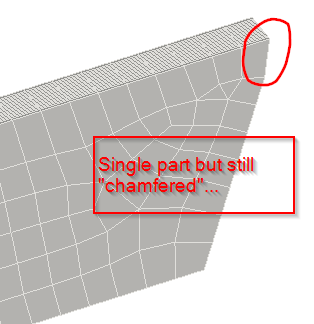
And one more thing... Even when I try to mesh a single c-channel part only, still there's the "chamfer" at the both ends of the c-channel. M.
Message 5 of 11
06-18-2014
07:26 AM
- Mark as New
- Bookmark
- Subscribe
- Mute
- Subscribe to RSS Feed
- Permalink
- Report
06-18-2014
07:26 AM
Martin,
I think the chamfer that shows up is due to ASIM having difficulty with the angle on the end of your channel. Look at the midplanes with lines.png file. I have drawn a line in pink where ASIM believes the midplane is. Notice that it is not extending the midplane line of each channel to meet the other channel. It just finds the midplane of each part and leaves it as is.
The way to move the edges so you have the part you want is to set "select lines", grab all the lines along one edge of your floating chamfer, perform a "move or copy" with "move ends" selected. You can then select the correct distance you want the edge to move. Do the same with the edge lines on the other channel. For that move you can just select the vector and snap from the edge you want to move to the other one you've already moved. That should close your c-channel assembly correctly.
When you make the manual moves, you will get the warning that you've see already, but you can ignore that. It has nothing to do with solid or midplane meshing. Just make sure that when you do the manual moves you don't re-mesh the model. If you do, it will revert to the original configuration. It is best to do the manual moves once you've completed all the automeshing. I went through this process myself on a sample model, and the model ran just fine.
I have included a picture of the edge move process from my sample model.
Stefan
Message 6 of 11
06-27-2014
06:30 AM
- Mark as New
- Bookmark
- Subscribe
- Mute
- Subscribe to RSS Feed
- Permalink
- Report
06-27-2014
06:30 AM
Hi Stefan!
Sorry again for my very late response. That was what I needed to know - to move the edge using the "move or copy" command with "move ends" option. Previously I used the Move (Point Move) command and therefore I was forced to remesh the model.
Thank you!
Martin
Message 7 of 11
06-27-2014
07:14 AM
- Mark as New
- Bookmark
- Subscribe
- Mute
- Subscribe to RSS Feed
- Permalink
- Report
06-27-2014
07:14 AM
OK, the bad news are here... The simulation still fails with some nice messages, see below:
SUMMARY:
**** DYNAMIC NODAL LOADS
ERROR - Unable to process model.
Error occurred with module: C:\Program Files\Autodesk\Simulation 2015\srunx.exe
LOG:
**** BEGIN NODAL DATA INPUT
30190 NODES
ERROR - Unable to process model.
CHECK MODEL:
The model contains errors due to geometry problems.
In working on FEM file for a FEA model
Terminal Error: FEM2ESH#108
make sure it is mid-plane mesh (varying thickness?) 6
2014/06/27-16:10:27
Nevertheless, I think we can skip this topic...
Message 8 of 11
06-27-2014
07:53 AM
- Mark as New
- Bookmark
- Subscribe
- Mute
- Subscribe to RSS Feed
- Permalink
- Report
06-27-2014
07:53 AM
Hi Martin,
My colleague Pat made a post a few months back with a list of all the FEM2ESH errors that have been encountered by technical support over the years, here is the information available on FEM2ESH#108.
Error Message: Terminal Error: FEM2ESH#108, FEMAPI#1
Decoding Processor: FEM2ESH Error Number: 108
Decoding Module: FEMAPI Part Number: 1
Error Description and Proposed Solution:
Define the thickness after mid-plane meshing a part.
Was the thickness for all parts with a midplane mesh define beforehand?
______________________________________________________________
If my post answers your question, please click the "Accept as Solution" button. This helps everyone find answers more quickly!
Andrew Sartorelli - Autodesk GmbH
Message 9 of 11
06-30-2014
05:16 AM
- Mark as New
- Bookmark
- Subscribe
- Mute
- Subscribe to RSS Feed
- Permalink
- Report
06-30-2014
05:16 AM
Hi Andrew,
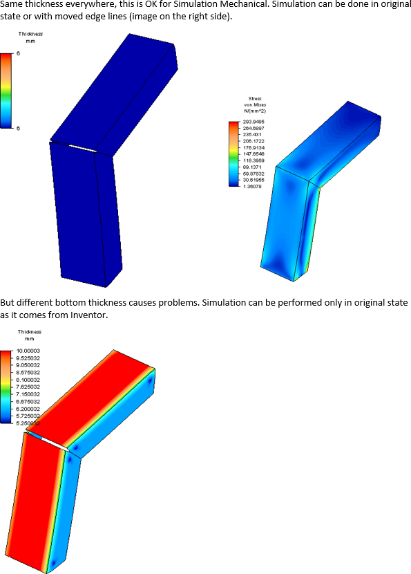
I think I have found what causes the error message. It is because of the different thickness of the c-channel bottom and side walls. For example, if the c-channel bottom will have the thickness of 10 mm and sides will have the thickness of 6 mm, Simulation Mechanical is not able to handle this situation after the changes to the mesh have been made manually by moving the edge lines of the midplane mesh. If the c-channel has the same thickness on its bottom as well as on its sides, I can manually move the edge of mesh and Simulation Mechanical is able to run the simulation correctly again. Please, take a look at some pictures attached.
If I think about it further, does this mean that midplane meshing should not be used for geometry with different thickness? Although the thickness of the c-channel is distributed uniformly across the part (same at the bottom and same on the side walls...).
Best regards,
Martin.
Message 10 of 11
08-26-2014
02:26 PM
- Mark as New
- Bookmark
- Subscribe
- Mute
- Subscribe to RSS Feed
- Permalink
- Report
08-26-2014
02:26 PM
One thing I have learned is that you can cheat your 3d model so that your midplanes will match up perfectly when created. ie overlap your 3d model parts by half the thickness of each C channel or increase your mesh matching and feature matching tolerances. (First search them on the help menu.) If you go to large the mesher starts jumping too large of gaps. Or if its a simple assembly do a brick mesh and try to get 3 elements across the thickess of the c channel and your results wont be bad and you wont have midplane mesh headaches of going from a good real life 3d model to a midplane model.
After reviewing all the model I would create a conservative constant thickness channel with no fillets. But in something this simple and small do a brick 3d mesh if you want to accurately portray stress concentrations of the tapered multithickness channel profile.
Message 11 of 11
09-03-2014
06:25 AM
- Mark as New
- Bookmark
- Subscribe
- Mute
- Subscribe to RSS Feed
- Permalink
- Report
09-03-2014
06:25 AM
Hello,
thanks for the reply. I'm afraid that overlapping the model won't be acceptable for my customer. Brick meshing might be worth trying but the assembly does not seems to be simple...
Martin
Reply
Topic Options
- Subscribe to RSS Feed
- Mark Topic as New
- Mark Topic as Read
- Float this Topic for Current User
- Bookmark
- Subscribe
- Printer Friendly Page
