Community
- Forums Home
- >
- Community Archive - Read Only
- >
- Simulation Mechanical Community
- >
- Simulation Mechanical Forum
- >
- Re: steady state heat transfer
Simulation Mechanical Forums (Read-Only)
Welcome to Autodesk’s Simulation Mechanical Forums. Share your knowledge, ask questions, and explore popular Simulation Mechanical topics.
Turn on suggestions
Auto-suggest helps you quickly narrow down your search results by suggesting possible matches as you type.
Reply
Topic Options
- Subscribe to RSS Feed
- Mark Topic as New
- Mark Topic as Read
- Float this Topic for Current User
- Bookmark
- Subscribe
- Printer Friendly Page
Message 1 of 18
Anonymous
1629 Views, 17 Replies
08-22-2011
02:14 AM
- Mark as New
- Bookmark
- Subscribe
- Mute
- Subscribe to RSS Feed
- Permalink
- Report
08-22-2011
02:14 AM
steady state heat transfer
can any body sort it out.
whenever i perform steady state heat transfer, result shows the body initial temperature 0 degree C even i wrote 20 degree C in default nodal temperature, i'm applying 50 degree see to my model and it contain 8 parts; 6 solid and 2 liquid.
17 REPLIES 17
Message 2 of 18
08-22-2011
05:16 AM
- Mark as New
- Bookmark
- Subscribe
- Mute
- Subscribe to RSS Feed
- Permalink
- Report
08-22-2011
05:16 AM
Hello,
I do not have any explanation. What version are you using? In particular, what loads do you have applied to your model?
More importantly, do the results look to be correct? Technically, the initial temperature in a steady state solution does not affect the results. You can put in an initial temperature of 1E6 degrees, and the results will be the same after an infinite amount of time (steady state). Providing a reasonable initial temperature can be beneficial when temperature dependent material properties or surface radiation are included in the analysis; the initial temperature provides a "seed" value to speed up the convergence iterations.
John Holtz, P.E.
Global Product Support
Autodesk, Inc.
If not provided already, be sure to indicate the version of Inventor Nastran you are using!
"The knowledge you seek is at knowledge.autodesk.com" - Confucius 😉
Message 3 of 18
08-22-2011
06:11 AM
- Mark as New
- Bookmark
- Subscribe
- Mute
- Subscribe to RSS Feed
- Permalink
- Report
08-22-2011
06:11 AM
i'm using autodesk simulation 2012, i apply a load ''applied temperature '' to a surface 50degree then i also mention default nodal temperature 20 degree in analysis parameter but still my result starts from zero degree,
Message 4 of 18
Anonymous
in reply to:
Anonymous
08-22-2011
06:29 AM
- Mark as New
- Bookmark
- Subscribe
- Mute
- Subscribe to RSS Feed
- Permalink
- Report
08-22-2011
06:29 AM
i wish the top plate should be at surrounding temperature 20 degree, i am applying 50 degree at the bottom, in the middle the chamber contain air. there will be conduction in the bottom plate then heat will transfer to the air enclosed in chamber. i generated fluid inside the chamber. i'm also bit confused either i'll apply convection load to solid surface which interact with fluid or i'll apply convection load to fluid surface which is adjacent to hot solid temperature. due to convection the temperature of air will increase then it will interact with top plate which should be at 20 degree and heat will be transfer again. i hope it can give an understanding.
there is also a piston inside the chamber but i got a reply from autodesk advisor that it will not work, coupling is only for fluid flow and heat transfer in multiphysics
Message 5 of 18
08-22-2011
08:13 AM
- Mark as New
- Bookmark
- Subscribe
- Mute
- Subscribe to RSS Feed
- Permalink
- Report
08-22-2011
08:13 AM
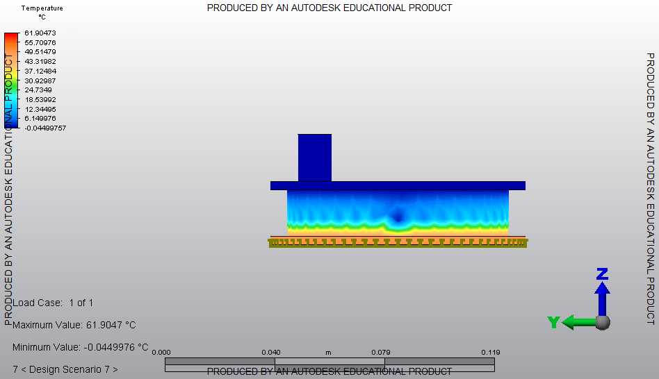
Thanks for the image. It helps to explain what is going on. Here are a number of things for you to consider.
- I think you are confusing the initial temperature ("Setup > Thermal Loads > Initial Temperature" and "Setup > Model Setup > Parameters > Options", both which set the temperature AT TIME 0) and the calculated temperature which is shown in your image. As mentioned before, the calculated temperature ("Results Contours > Temperature > Calculated Temperature") is at time infinity in a steady state analysis, and the calculated temperatures are not affected by the initial temperature. For what it is worth, the "Results Contours > Temperature > Initial Temperature" should show the model shaded with temperatures of 20 degrees.
- Did you get any warning messages from the analysis? If so, go to the Report tab and choose to view the log file or summary file to find the warnings.
- Based on your written description, the model has a source of heat (50 degree applied temperature, "Setup > Thermal Loads > Controlled Temperature") but no means of removing the heat. Therefore, a steady state thermal analysis should have heated the model to a uniform temperature. Sometimes the analysis does this; other times, it gives a warning that the solution is unstable, or missing a load, or there may not be a unigue solution, or something like that, but it gives a result which is not accurate. (Garbage in, garbage out.)
- For the "surrounding temperature of 20 degrees" that you wrote about for the top, you should apply a load that represents this. A convection load ("Setup > Thermal Loads > Convectin") is usually the type of load that simulates this the best since you know what surrounds the model (air?), the orientation of the surface (horizontal?), and the approximate temperature of the part (less than 50 degrees?), so the convection coefficient can be calculated.
- If doing just a "Thermal > Steady-State Heat Transfer" analysis, you do not want to apply a convection load to the inside chamber. Most loads in thermal analysis represent a transfer of heat from/to the model and the environment. That is, it adds or removes heat from the model. In your situation, heat is being transferred from one part to another; it is not escaping the model.
- The best that can be done with the internal air pocket in Thermal analysis is to let the internal air conduct the heat across the air chamber. Depending on what the analysis represents, this may be sufficient, but the thermal conductivity of the air probably needs to be increased to represent the air currents that exist in reality.
- I do not know if the educational version includes the analysis type "Multiphysics > Steady Coupled" or "Multiphysics > Transient Coupled" or not. Those two analysis types will calculate the air currents (convective loads) that occur in the internal air chamber.
Hope this gives you some ideas. Don't hesitate to ask for additional ideas 🙂
John Holtz, P.E.
Global Product Support
Autodesk, Inc.
If not provided already, be sure to indicate the version of Inventor Nastran you are using!
"The knowledge you seek is at knowledge.autodesk.com" - Confucius 😉
Message 6 of 18
08-22-2011
08:33 AM
- Mark as New
- Bookmark
- Subscribe
- Mute
- Subscribe to RSS Feed
- Permalink
- Report
08-22-2011
08:33 AM
thanks i'm trying these, can u also tell me about contact type, there is an option in tree at the bottom e.g bonded, surface contact. Do i need to choose any of these for my model or i should go on by default bonded. as i told you these is a piston inside the chamber, for fluid flow as well so the air stream should not intersect the piston.
Is it possible to move the piston in multiphysics, thermal or fluid flow analysis due to air pressure?
i may have few more questions but first i'm going to try your suggestions.
onething more when i get result and try to generate graphs, my software stuck and some time it corrupts the file.
when i try to make streamlines in fluid, it always stuck for a while.
Message 7 of 18
08-24-2011
07:38 AM
- Mark as New
- Bookmark
- Subscribe
- Mute
- Subscribe to RSS Feed
- Permalink
- Report
08-24-2011
07:38 AM
(there is an option in tree at the bottom e.g bonded, surface contact. )
A: Contact is talking about the surface relations between parts.
-Welded: same as bonded, two parts are fully connected like a single part
-Free/No contact: two parts have no connections
-Surface contact: can define contact “total thermal resistance” between two surfaces
(Is it possible to move the piston in Multiphysics, thermal or fluid flow analysis due to air pressure?)
A: We don’t support two-way FSI (fluid-solid interaction) in Multiphysics, however, one work around is that user can do multiple steps using one way FSI.
(when i try to make streamlines in fluid, it always stuck for a while.)
A: Using finer mesh will help, and it needs enhancement in our POST as well.
Jianhui Xie, Ph.D
Principal Engineer
MFG-Digital Simulation
Principal Engineer
MFG-Digital Simulation
Message 8 of 18
08-24-2011
07:51 AM
- Mark as New
- Bookmark
- Subscribe
- Mute
- Subscribe to RSS Feed
- Permalink
- Report
08-24-2011
07:51 AM
(i told you these is a piston inside the chamber, for fluid flow as well so the air stream should not intersect the piston.)
A: The thermal contact between air stream and solid part usually set to be bonded since the fluid makes very good contact with solid surface, however, if there are coating on the solid part surface but the coating layer is not modeled, the fluid-solid contact should be considered. In comparison, the roughness in solid to solid surface makes imperfect contact, thus needs to provide thermal resistance between parts.
Jianhui Xie, Ph.D
Principal Engineer
MFG-Digital Simulation
Principal Engineer
MFG-Digital Simulation
Message 9 of 18
08-31-2011
04:14 PM
- Mark as New
- Bookmark
- Subscribe
- Mute
- Subscribe to RSS Feed
- Permalink
- Report
08-31-2011
04:14 PM
i'm still facing problem, as i told you earlier. the default nodal temperature in my autodesk does not work, my results shows temperature zero degree, although i set default nodal 20 degree.
applied temperature 50 degree
now i removed fluid convection as well
kindly see below ds.lgs
Autodesk (R) Simulation Steady-State Heat Transfer
Version 2012.01.00.0017-W64/X64 15-Jun-2011
Copyright (c) 2011, Autodesk, Inc. All rights reserved.
**** Memory Dynamically Allocated = 1928538 KB
**** Steady-State Heat Transfer Analysis
----------------------------------------------------------------
DATE: AUGUST 31, 2011
TIME: 11:27 PM
Input Model: C:\Users\Ikhlas\Documents\Final Project\acad\789.ds_data\11\ds
PROGRAM VERSION: 201201000017
ALG.DLL VERSION: 201201000017
AlgConfig.DLL VERSION: 201201000017
Agsdb_AR.DLL VERSION: 201201000017
AMGSolve.DLL VERSION: 201201000017
AlgSolve.DLL VERSION: 201201000017
----------------------------------------------------------------
Options executed are:
NOMIN
SUPSTR
processing ...
**** Model Unit System Settings:
--------------------------------------------
Unit System : Custom
Force : N
Length : mm
Time : s
Temperature (Absolute) : deg C (K)
Thermal Energy : J
Voltage : V
Current : A
Electrical Resistance : ohm
Mass : N*s^2/mm
--------------------------------------------
**** OPENING TEMPORARY FILES
NDYN = 10
**** BEGIN NODAL DATA INPUT
Node number= 256493
Equation number= 256493
**** END NODAL DATA INPUT
**** HARD DISK FILE SIZE INFORMATION FOR PROCESSOR:
Available hard disk space on C drive = 115292.543 megabytes
**** BEGIN NODAL HEAT FLOW INPUT
**** END NODAL HEAT FLOW INPUT
**** BEGIN TYPE-39 DATA INPUT
3158 ELEMENTS ...
**** END TYPE-39 DATA INPUT
**** BEGIN TYPE-39 DATA INPUT
8795 ELEMENTS ...
**** END TYPE-39 DATA INPUT
**** BEGIN TYPE-39 DATA INPUT
3270 ELEMENTS ...
**** END TYPE-39 DATA INPUT
**** BEGIN TYPE-39 DATA INPUT
106516 ELEMENTS ...
**** END TYPE-39 DATA INPUT
**** BEGIN TYPE-39 DATA INPUT
8350 ELEMENTS ...
**** END TYPE-39 DATA INPUT
**** BEGIN TYPE-39 DATA INPUT
8876 ELEMENTS ...
**** END TYPE-39 DATA INPUT
**** BEGIN TYPE-39 DATA INPUT
43396 ELEMENTS ...
**** END TYPE-39 DATA INPUT
**** BEGIN TYPE-39 DATA INPUT
11279 ELEMENTS ...
**** END TYPE-39 DATA INPUT
**** BEGIN TEMPERATURE ELEMENT DATA INPUT
573 ELEMENTS ...
**** END TEMPERATURE ELEMENT DATA INPUT
**** Fixing loads ...
**** Invoking BCSLIB-EXT Sparse Solver ...
**** End solution
**** BEGIN TYPE-39 DATA INPUT
3158 ELEMENTS ...
**** END TYPE-39 DATA INPUT
**** BEGIN TYPE-39 DATA INPUT
8795 ELEMENTS ...
**** END TYPE-39 DATA INPUT
**** BEGIN TYPE-39 DATA INPUT
3270 ELEMENTS ...
**** END TYPE-39 DATA INPUT
**** BEGIN TYPE-39 DATA INPUT
106516 ELEMENTS ...
**** END TYPE-39 DATA INPUT
**** BEGIN TYPE-39 DATA INPUT
8350 ELEMENTS ...
**** END TYPE-39 DATA INPUT
**** BEGIN TYPE-39 DATA INPUT
8876 ELEMENTS ...
**** END TYPE-39 DATA INPUT
**** BEGIN TYPE-39 DATA INPUT
43396 ELEMENTS ...
**** END TYPE-39 DATA INPUT
**** BEGIN TYPE-39 DATA INPUT
11279 ELEMENTS ...
**** END TYPE-39 DATA INPUT
**** BEGIN TEMPERATURE ELEMENT DATA INPUT
573 ELEMENTS ...
**** END TEMPERATURE ELEMENT DATA INPUT
**** BEGIN TYPE-39 HEAT FLUX CALCULATIONS
3158 ELEMENTS ...
**** END TYPE-39 HEAT FLUX CALCULATIONS
**** BEGIN TYPE-39 HEAT FLUX CALCULATIONS
8795 ELEMENTS ...
**** END TYPE-39 HEAT FLUX CALCULATIONS
**** BEGIN TYPE-39 HEAT FLUX CALCULATIONS
3270 ELEMENTS ...
**** END TYPE-39 HEAT FLUX CALCULATIONS
**** BEGIN TYPE-39 HEAT FLUX CALCULATIONS
106516 ELEMENTS ...
**** END TYPE-39 HEAT FLUX CALCULATIONS
**** BEGIN TYPE-39 HEAT FLUX CALCULATIONS
8350 ELEMENTS ...
**** END TYPE-39 HEAT FLUX CALCULATIONS
**** BEGIN TYPE-39 HEAT FLUX CALCULATIONS
8876 ELEMENTS ...
**** END TYPE-39 HEAT FLUX CALCULATIONS
**** BEGIN TYPE-39 HEAT FLUX CALCULATIONS
43396 ELEMENTS ...
**** END TYPE-39 HEAT FLUX CALCULATIONS
**** BEGIN TYPE-39 HEAT FLUX CALCULATIONS
11279 ELEMENTS ...
**** END TYPE-39 HEAT FLUX CALCULATIONS
**** Table for actual hard disk space used:
ds.t7 = 2003.859 kilobytes
ds.t8 = 11066.250 kilobytes
ds.t9 = 41.250 kilobytes
ds.t10 = 41.250 kilobytes
ds.t11 = 403086.422 kilobytes
ds.t12 = 0.000 kilobytes
ds.t13 = 41.250 kilobytes
ds.t14 = 0.562 kilobytes
ds.t15 = 41.250 kilobytes
ds.t18 = 41.250 kilobytes
ds.t65 = 2003.859 kilobytes
ds.t67 = 102639.617 kilobytes
total temporary disk storage (megabytes) = 508.796
**** BEGIN DELETING TEMPORARY FILES
**** TEMPORARY FILES DELETED
**** END OF SUCCESSFUL EXECUTION
Processing completed for model C:\Users\Ikhlas\Documents\Final Project\acad\789.ds_data\11\ds
ds.l10 = 3.885 kilobytes
ds.to = 12023.156 kilobytes
ds.hfo = 6807.828 kilobytes
Total actual hard disk space used = 533.837 megabytes
Total elapsed time = 25.635 minutes
Message 10 of 18
09-01-2011
05:45 AM
- Mark as New
- Bookmark
- Subscribe
- Mute
- Subscribe to RSS Feed
- Permalink
- Report
09-01-2011
05:45 AM
Hi chikhlas,
Either your description is inaccurate, or your model is setup incorrectly. I believe you are confusing the default nodal temperature with the minimum calculated temperature. As I tried to explain before, the default temperature that you entered under the Analysis Parameters dialog has absolutely no affect on the calculated temperatures in steady-state heat transfer. So, the minimum calculated temperature of 0 degrees shown in your image "model.jpg" (attached to the 8-22-2011 post) is not related to the 20 degrees default temperature you applied. In the results environment, go to "Results Contours > Temperature > Initial Temperature" on the ribbon; you will see the entire model is 20 degrees.
For the calculated temperature results, one possibility is that you have some other load applied to the model that is forcing the temperature to be 0. Another possibility is the solution is wrong because you only have 1 load applied (the 50 degrees on the bottom surface). Another possibility is that the top plate is not connected to the lower stuff, so heat cannot transfer from below to the top. (I am basing this last possibility on the model.jpg image you posted.)
I think that neither the log file (ds.Lgs) or summary file (ds.L10) contains the data necessary to determine the problem. So you will either need to send the model to technical support, or we can try to get the file small enough to post to this forum (the limit is 2 or 3 MB if I remember correctly), or post it to a common site like DropBox (www.dropbox.com) or You Send It (www.yousendit.com). Here's what you should do to get the archive as small as possible. Follow each step carefully so that you do not accidentally destroy your real model!
- Save the model to a new name. [With the model open, click the "S" application button, then "Save As". Give the model a new name like "initial temperature".]
- Delete all of the design scenarios except for 11 in the new model. [This is the design scenario you showed in your log file. Click the first design scenario in the browser, hold the shift key, and click the last design scenario before 11. Right-click on one of the selections and choose "Delete".]
- Use Windows Explorer (My Computer) to navigate to the folder containing the model. Then navigate to the "initial temperature.ds_data\11\ds.mod" folder.
- Delete all of the files EXCEPT for model.cdx, model.dbf, and model.ftp. [Depending on your Windows Explorer, the extensions may not be shown. But there are only three files named "model", so delete everything else.]
- Archive the model only. [In Autodesk Simulation, click the "S" application button, then "Archive > Create > Model Only".]
- Post the archive file ("initial temperature.ach") somewhere. Attach to this forum if it is smaller than whatever the limit is.
Thanks.
John Holtz, P.E.
Global Product Support
Autodesk, Inc.
If not provided already, be sure to indicate the version of Inventor Nastran you are using!
"The knowledge you seek is at knowledge.autodesk.com" - Confucius 😉
Message 11 of 18
09-01-2011
06:44 AM
- Mark as New
- Bookmark
- Subscribe
- Mute
- Subscribe to RSS Feed
- Permalink
- Report
09-01-2011
06:44 AM
where can i send this file? can you confirm me any e-mail address, for support team ... because it is not possible to upload file here in this forum due to size limit
Message 12 of 18
09-13-2011
08:43 AM
- Mark as New
- Bookmark
- Subscribe
- Mute
- Subscribe to RSS Feed
- Permalink
- Report
09-13-2011
08:43 AM
Hi,
I feel that it is better for you to setup a smaller model to test your issue. It will help you to identify the problem too. If you still observe the similar behavior, then you can attach the smaller model so that we can take a look.
hupe
Message 13 of 18
07-03-2012
09:16 AM
- Mark as New
- Bookmark
- Subscribe
- Mute
- Subscribe to RSS Feed
- Permalink
- Report
07-03-2012
09:16 AM
I see this thread has not been updated in a while but I am having essentially the same problem. I simplified it down to a beam with an applied temperature on each end of the beam (different temperatures). I seem to get the 0°C part temperature when my mesh size is too small or conversely I have too many elements. I have not confirmed if it is one or the other. It seems my threshold is approximately 100,000 elements. I saw from the log in this thread that the OP had over 200,000 elements. Is there a resolution to this problem?
Message 14 of 18
04-09-2013
05:40 AM
- Mark as New
- Bookmark
- Subscribe
- Mute
- Subscribe to RSS Feed
- Permalink
- Report
04-09-2013
05:40 AM
John,
I'm like the previous author (cekel). I've only been using the thermal facility of ASM for about 24 hours so I haven't tried everything. What I've been doing is applying several convection and radiant loads to a flat steel plate (600mmx600mmx10mm thick). The ambient temperature within both of these dialog boxes has been set to 40 deg C. On a number of my runs, I've noticed that parts of the model were 0 deg C as well??
I'm using 2013SP2.
One thing I haven't done in every cas is to apply convection/radiation loads to every surface. Some times, I've left the thin edges without anything. Not sure if this is a problem. I assumed it means they become insulated.
Tonight, I revisited my model. I had over 200 000 elements with 4 elements thru thickness. I dropped this to about 30 000 elements (2 thru thickness). No difference! I got a minimum of -78 deg C. Should have been close to 40 deg C.
Next i switched off midside nodes, no other change. Got minimum of +91 deg C which is probably ok.
Your thoughts?
Tim
Message 16 of 18
04-09-2013
05:48 AM
- Mark as New
- Bookmark
- Subscribe
- Mute
- Subscribe to RSS Feed
- Permalink
- Report
04-09-2013
05:48 AM
I had this problem addressed in another thread. The suggestion in that thread was:
My guess is that you can get accurate results by reducing the "Stiffness" of the Controlled Temperatures. According to the documentation, the stiffness should be "(2-3 orders of magnitude higher than the conductivity of the materials in your model)".
This worked for me. Good luck
Message 17 of 18
04-09-2013
09:44 PM
- Mark as New
- Bookmark
- Subscribe
- Mute
- Subscribe to RSS Feed
- Permalink
- Report
04-09-2013
09:44 PM
cekel,
thanks for this. I couldn't check this because I'm not using any controlled temperatures. I still have the problem.
Any suggestions?
Message 18 of 18
04-12-2013
09:14 AM
- Mark as New
- Bookmark
- Subscribe
- Mute
- Subscribe to RSS Feed
- Permalink
- Report
04-12-2013
09:14 AM
Hi,
We need to know a whole lot more about your model. For example,
- Oops. I see from the subject line that you are performing steady state. Sorry.
Are you performing steady state or transient heat transfer? - If the ambient conditions are 40 degrees, wouldn't the solution be 40 degrees? Oh, you have other loads that are causing heat?
 What are the other loads?
 - What is the input for each of the loads?
- Since you have radiation in the analysis, the solution is nonlinear and requires iterations to converge. Is it converging? Does it reach the maximum number of iterations that you specified and just continues with a bogus answer? What is your input for the convergence? ("Setup > Model Setup > Parameters > Advanced" tab if I remember correctly.)
As Cekel indicated, extreme input can be a cause of the problem, such as a large stiffness with a controlled temperature, or a large convection coefficient used to "hold" the temperature at some location.
Another problem that can occur is when heat enters a face of an element and flows out a face that is perpendicular to the inlet face. (Normally, some heat passes out the face that is opposite from the inlet face.) The discussion around Figure 2 on the page "Thermal Results Menu" in the documentation talks about the heat rate issue. This heat issue can lead to strange temperature results like you are seeing. If this is the culprit, either
- ignore those elements,
- adjust the heat loads so that the heat is not trying to pass through perpendicular faces. For example, instead of extending the heating load over the entire area, split the surface so that you can apply it to the inner 90% of the surface,
- try a finer mesh in the area. This may lead to even higher temperatures which indicates that you have a mathematical "singularity".
- Is there some way to "help" the heat travel in a smooth path? If the problem is like Figure 2 that I referenced, would a rounded corner (and finer mesh) help the heat to flow better?
Reply
Topic Options
- Subscribe to RSS Feed
- Mark Topic as New
- Mark Topic as Read
- Float this Topic for Current User
- Bookmark
- Subscribe
- Printer Friendly Page
