Community
- Forums Home
- >
- Community Archive - Read Only
- >
- Simulation Mechanical Community
- >
- Simulation Mechanical Forum
- >
- Re: Problems with Simulation Representation
Simulation Mechanical Forums (Read-Only)
Welcome to Autodesk’s Simulation Mechanical Forums. Share your knowledge, ask questions, and explore popular Simulation Mechanical topics.
Turn on suggestions
Auto-suggest helps you quickly narrow down your search results by suggesting possible matches as you type.
Problems with Simulation Representation
7 REPLIES 7
Reply
Topic Options
- Subscribe to RSS Feed
- Mark Topic as New
- Mark Topic as Read
- Float this Topic for Current User
- Bookmark
- Subscribe
- Printer Friendly Page
Message 1 of 8
12-17-2012
05:46 PM
- Mark as New
- Bookmark
- Subscribe
- Mute
- Subscribe to RSS Feed
- Permalink
- Report
12-17-2012
05:46 PM
Problems with Simulation Representation
Hi,
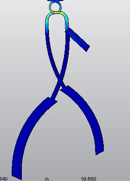
I am trying to do a brief study on optimizing the design of two members being forced downward into each other through the use of a sliding member. I have the part set up and constrained so that it deflects the arm members down partially but they always get stopped at a certain point. As I increase the force on the sliding member, the displacement value grows, however the video representation still always stops the piece at the same place and does not fully deform the two arms as should be. Is there a simple time step or something that I just cannot find that stops the force process on the sliding member after a set time.
As the image shows I apply the downward force to the sliding piece and it should collapse the arms inward but always stops at the point shown...
Any help would be greatly appreciated!
Thanks,
Kyle
7 REPLIES 7
Message 2 of 8
12-17-2012
06:45 PM
- Mark as New
- Bookmark
- Subscribe
- Mute
- Subscribe to RSS Feed
- Permalink
- Report
12-17-2012
06:45 PM
Hi kyle,
Assuming you are using MES analysis, you can specify the magnitude of your applied force with a time dependent behavior. This can be applied in Analysis Parameters>Load Curves. You will have to make sure that your force is specified with a load curve which covers the whole duration of the analysis.
If that does not help it, I can only guess that the force that you applied is not enough to overcome the bending stiffness of your part, which is why it stopped. I would suggest that you use Presribed Displacement on your sliding member to move it to its final position. The forces required will then be determined by the software.
Regards
Ilyas
Message 3 of 8
12-17-2012
08:33 PM
- Mark as New
- Bookmark
- Subscribe
- Mute
- Subscribe to RSS Feed
- Permalink
- Report
12-17-2012
08:33 PM
Yes, I've tried the prescribed displacement already too. All I want if for that slider piece to continue all the way down to where it stops on the the steps because it can be pushed down no futher. This process of forcing down the slider pushes the arms in towards each other. It is a simple command and i just cannot get it do this. I want to be able to look at the stresses in the loop when I do this in order to optimize the design and beef up the loop some if need be in areas of high stress.
I've attached another picture to help demonstrate the simple feature I need.
Thanks again,
Kyle
Message 4 of 8
12-18-2012
12:48 AM
- Mark as New
- Bookmark
- Subscribe
- Mute
- Subscribe to RSS Feed
- Permalink
- Report
12-18-2012
12:48 AM
Now I am puzzled as to what your problem is. Did the analysis successfully finish? Or did the analysis stop midway with an error? Or did the analysis finish but the loop has not completed its path?
If you used the prescribed displacement on the top surface of the loop to push it down to the final position of the event, then the software will definitely move it there regardless of the required force. Unless of course, the load curve is not covered by the event.
Regards
Ilyas
Message 5 of 8
12-18-2012
08:33 AM
- Mark as New
- Bookmark
- Subscribe
- Mute
- Subscribe to RSS Feed
- Permalink
- Report
12-18-2012
08:33 AM
First off I want to thank you for your help thus far.
As I apply more downward force on the sliding member the displacements values do increase on the arms as they should since the downward slide force forces the arms themselves downwards and inwards until it reaches the step up in the part where it forces the sliding member to be stopped. However, every time I run the analysis and watch sliding member being forced down it only goes town about a total of a half an inch and then stops there. Where the sliding member should potentially have around 4-5 inches of downward or -y travel. Even when I set that in the prescribed displacement when I watch the playback of the part being deflected downward and inward it still only appears to travel down the same amount of about a half an inch and stop and not stress the loop as it would if the sliding piece really translated down the whole 4-5 inches of travel that it can.
Does this make any sense and also if it would help I could maybe send the step file to you with what I am seeing if it helps explain the issue?
Thanks again,
Kyle
Message 6 of 8
12-18-2012
09:28 AM
- Mark as New
- Bookmark
- Subscribe
- Mute
- Subscribe to RSS Feed
- Permalink
- Report
12-18-2012
09:28 AM
Hi Kyle,
It is not clear yet what your analysis is doing.
- Did the analysis finish successfully? Do the results show all time steps?
- Or did the analysis stop midway with an error? If so, what is the error? (The log file is visible from the Report tab.)
- Or did the analysis finish but the loop has not completed its path? (Load curve is wrong.)
- Is the displacement value shown in the legend okay but the slider "halts" in the image? (Displacement scale needs to be set to an absolute value of 1 instead of a percentage such as 5%.)
It may be necessary to post an archive of your model. Please search this discussion group for "Create Post Archive" and you will find a thread with the instructions.
Message 7 of 8
12-18-2012
06:34 PM
- Mark as New
- Bookmark
- Subscribe
- Mute
- Subscribe to RSS Feed
- Permalink
- Report
12-18-2012
06:34 PM
These I think are the errors from the log:
Warning: Shear modulus 1.139E+05 is inconsistent with 1.259E+05 calculated from the
elastic modulus and Poisson ratio for isotropic material part 1.
Note: Material is not truly isotropic
**** CONTACT ELEMENT DATA
propID= 1 Contact Stiffness = 2.9700E+07
1 2.9700E+07
I tried the 4th suggestion in regards to the scale and it just stretches the object to an unbelievable amount for the little force I have. And the slider piece and the arms don't follow the contact specified in the study. As the picture shows on this attachement when I scale to 100%. The slider piece should always remain fixed on the y axis with the arms inside the slot until the slider piece is stopped at the bottom by the steps?
All I am trying to do is see the stresses on the loops which are connected to the top fixed piece as the slider piece goes through its motion from top to bottom position to see where I need to beef up the part some and anaylze it with different materials.
Thanks again!
Kyle
Message 8 of 8
12-18-2012
07:32 PM
- Mark as New
- Bookmark
- Subscribe
- Mute
- Subscribe to RSS Feed
- Permalink
- Report
12-18-2012
07:32 PM
Hi Kyle,
It is very hard to deduce things from the image provided. You might consider to notch down a bit on the cropping, perhaps you might show the legend and annotation as well.
I do not know much on the mechanics of materials or how the software treats shear modulus, but I am not able to recreate the warning that you showed in a MES analysis. In other words, I think you are using the wrong analysis type. Plus, as you followed John's 4th instrucion, you find that the object stretches to an "unbelievable amount". This can only mean that you are using a Linear Static Stress analysis.
Here is an 20 minute video that can help guide you on performing your analysis. The model may not be similar, but the concept of motion and contact is.
http://vp.telvue.com/preview?id=T01885&video=59716
I hope this helps.
Regards
Ilyas
Reply
Topic Options
- Subscribe to RSS Feed
- Mark Topic as New
- Mark Topic as Read
- Float this Topic for Current User
- Bookmark
- Subscribe
- Printer Friendly Page
