Community
- Forums Home
- >
- Community Archive - Read Only
- >
- Simulation Mechanical Community
- >
- Simulation Mechanical Forum
- >
- Re: MES simulation issue
Simulation Mechanical Forums (Read-Only)
Welcome to Autodesk’s Simulation Mechanical Forums. Share your knowledge, ask questions, and explore popular Simulation Mechanical topics.
Turn on suggestions
Auto-suggest helps you quickly narrow down your search results by suggesting possible matches as you type.
Reply
Topic Options
- Subscribe to RSS Feed
- Mark Topic as New
- Mark Topic as Read
- Float this Topic for Current User
- Bookmark
- Subscribe
- Printer Friendly Page
Message 1 of 5
10-21-2013
02:39 AM
- Mark as New
- Bookmark
- Subscribe
- Mute
- Subscribe to RSS Feed
- Permalink
- Report
10-21-2013
02:39 AM
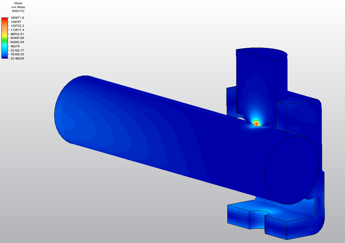
Am trying to find the stress and deformation on a copper wire, due to applied torque on the screw, which will thrust the copper wire.
I gave all the boundary condition and contact specification and simulated in MES environment.
The analysis is not running, if I apply a axial force on the bolt head (force generated due to applied torque)
Analysis runs good if I apply nodal displacement on the verities on the bold head surface.
I want to know why while giving force, analysis is not performing?.
Solved! Go to Solution.
Solved by sriramsheval. Go to Solution.
Solved by AstroJohnPE. Go to Solution.
Solved by AstroJohnPE. Go to Solution.
4 REPLIES 4
Message 2 of 5
10-21-2013
08:43 AM
- Mark as New
- Bookmark
- Subscribe
- Mute
- Subscribe to RSS Feed
- Permalink
- Report
10-21-2013
08:43 AM
Prescribe displacements (PD) will always result in a faster analysis in MES than force-based loads because the model is more stable. The PDs control the axial position of the bolt. A load does not add any stability to the analysis.
Also, part of the solution is already known when using PDs: the displacement at nodes X through X. With a force, no displacements are known, and the software needs to do the complete integration F = ma to find the displacements.
Since you have the complete answer from the PD simulation, there is no need to go back to the force analysis. But in the future when you may need to use a load, keep in mind that there is a difference between the analysis "not running" and the analysis running (converging) very slowly. 😉 What makes contact analyses slow running is the software needs to find the moment of contact. So based on the applied load at the time that the screw makes contact with the wire, and knowing the mass of the screw, you can calculate the acceleration. (a = F/m). Based on the acceleration, you can calculate how far the screw moves in one time step {d = (vo + a*time)*time step size, assuming constant acceleration}. If that distance is much larger than the contact distance (Sim Mechanical 2014) or contact tolerance (Sim Mechanical 2013 and older), then the processor needs to reduce the time step. Eventually, it detects when the contact occurs. For this reason, some users suggest that the force be ramped up slowly from 0 load to a small value. Once contact occurs, the load can be ramped more quickly to the full magnitude.
Then when you consider the vibration, deformation, and "chatter" of the contact between the parts, it can take many iterations to get through the time steps.
Reply
Message 3 of 5
10-29-2013
08:07 AM
- Mark as New
- Bookmark
- Subscribe
- Mute
- Subscribe to RSS Feed
- Permalink
- Report
10-29-2013
08:07 AM
John Holt,
Thanks you for making me aware on the difference between PD's and Force based load.
Meanwhile, I did the same analysis in "Static Structural analysis".
I found that the connection is not working, when the scenario is "static structural analysis"
As the connection between the parts didn't work in "static structural analysis", I assembled the assembly, as how it will when contact is established. I run the analysis with out defining the contact.
The analysis run well and got the results. Why Contact "Connection" didn't work in Static analysis. Is there any other option to be enabled.
Can such analysis be performed in Static or MES will only do?

Message 4 of 5
10-29-2013
10:46 AM
- Mark as New
- Bookmark
- Subscribe
- Mute
- Subscribe to RSS Feed
- Permalink
- Report
10-29-2013
10:46 AM
Hi again,
It is difficult to say what may have been wrong in the static analysis. Of course, you need to define which two surfaces, parts, or combination of parts and surface will come into contact. This step is similar to the MES analysis.
But one important factor to understand about static analysis is that only surface/nodes that are initially in contact with 0 load have the possibility of coming into contact. Two surfaces that are separated will never contact each other in static analysis. (Note that the mesher will remove small gaps between surfaces based on the user-entered tolerance located somewhere under "Mesh > Mesh > 3D Mesh Settings > Options".)
So if more area of the bolt/screw come into contact with the copper wire and it is screwed inward, MES is the best way to do the analysis.
Reply
Message 5 of 5
10-30-2013
04:43 AM
- Mark as New
- Bookmark
- Subscribe
- Mute
- Subscribe to RSS Feed
- Permalink
- Report
10-30-2013
04:43 AM
Thanks a lot John,
The information which you gave will help me carry out the analysis further.
Thanks again
Reply
Topic Options
- Subscribe to RSS Feed
- Mark Topic as New
- Mark Topic as Read
- Float this Topic for Current User
- Bookmark
- Subscribe
- Printer Friendly Page