Community
- Forums Home
- >
- Community Archive - Read Only
- >
- Simulation Mechanical Community
- >
- Simulation Mechanical Forum
- >
- Re: flow accelerates for unknown reason
Simulation Mechanical Forums (Read-Only)
Welcome to Autodesk’s Simulation Mechanical Forums. Share your knowledge, ask questions, and explore popular Simulation Mechanical topics.
Turn on suggestions
Auto-suggest helps you quickly narrow down your search results by suggesting possible matches as you type.
flow accelerates for unknown reason
5 REPLIES 5
SOLVED
Reply
Topic Options
- Subscribe to RSS Feed
- Mark Topic as New
- Mark Topic as Read
- Float this Topic for Current User
- Bookmark
- Subscribe
- Printer Friendly Page
Message 1 of 6
06-05-2012
06:01 AM
- Mark as New
- Bookmark
- Subscribe
- Mute
- Subscribe to RSS Feed
- Permalink
- Report
06-05-2012
06:01 AM
Hi all,
I'm a rookie in flow analysis using Autodesk simulation,
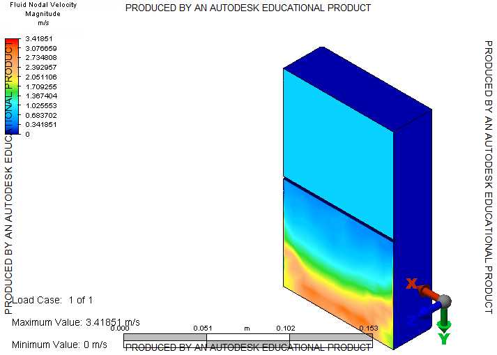
I've done a simple simulation of a fluid that flows through a header & saw that the velocity has increased.
I figured that it might be because of gravity's influence (although in the parameters gravity was not checked) or becuase the flow area has decreased so I made another analysis of a flow through a plain tube (no change in the flow area) and saw that the velocity also increased there, instead of decreased - again for unknown reason.
can anyone think of a possible reason?
inlet nodal velocity was 0.823m/sec
outlet velocity as attached
Thanks a lot.
Solved! Go to Solution.
Solved by John_Holtz. Go to Solution.
Solved by PipePakPat. Go to Solution.
Solved by PipePakPat. Go to Solution.
5 REPLIES 5
Message 2 of 6
06-05-2012
12:44 PM
- Mark as New
- Bookmark
- Subscribe
- Mute
- Subscribe to RSS Feed
- Permalink
- Report
06-05-2012
12:44 PM
It may be more appropriate to view the velocities in specific vector directions. Choose to view the velocities in the direction of the applied velocity. I suspect that tangential velocities may be participating in the magnitude. Also, fully developed fluid flow produces a parabolic velocity profile, where velocities are zero at the walls and their largest in the center of the flow field (for circular cross sections). Please let me know if you have further questions.
Pat Tessaro, P.E.
Premium Support Specialist – Simulation
Autodesk, Inc.
6425 Living Place
Suite 100
Pittsburgh, PA 15206
Premium Support Specialist – Simulation
Autodesk, Inc.
6425 Living Place
Suite 100
Pittsburgh, PA 15206
Message 3 of 6
06-06-2012
01:52 PM
- Mark as New
- Bookmark
- Subscribe
- Mute
- Subscribe to RSS Feed
- Permalink
- Report
06-06-2012
01:52 PM
Thanks a lot Pat for your response.
I''ve checked the velocity in the direction of the applied velocity and it did made a little difference,
and I also totaly accept the parabolic velocity profile issue, which explains why some of the flow will have higher velocity values.
is there a way for me to check a certain surface (a section) mean velocity (not by hand calculation it from the mass flow rate)?
Thanks again
Message 4 of 6
06-06-2012
02:12 PM
- Mark as New
- Bookmark
- Subscribe
- Mute
- Subscribe to RSS Feed
- Permalink
- Report
06-06-2012
02:12 PM
Set the displayed results type for velocities in the axial direction, then select the inlet or outlet surface then right-click and choose to select sub-entities, then nodes. One can then right-click and choose to inquire on results. A window will appear. Change the "Summary" type to "Mean". Please let me know if you have further questions.
(And if you suspect your original question has been solved, right-click on the post and mark it as solved for the benefit of other viewers.)
Pat Tessaro, P.E.
Premium Support Specialist – Simulation
Autodesk, Inc.
6425 Living Place
Suite 100
Pittsburgh, PA 15206
Premium Support Specialist – Simulation
Autodesk, Inc.
6425 Living Place
Suite 100
Pittsburgh, PA 15206
Message 5 of 6
06-06-2012
03:30 PM
- Mark as New
- Bookmark
- Subscribe
- Mute
- Subscribe to RSS Feed
- Permalink
- Report
06-06-2012
03:30 PM
Hi,
I think you should not be calculating the mean velocity at a surface if your goal is to check that the "flow" makes sense. The mean velocity depends on the mesh size at each node. Instead, you should look at the "Flow Rate through Face", turn "Results Contours > Smooth Results" off, then select the surface and "Results Inquire > Inquire > Current Results" and then sum the flow through all of the faces.
John Holtz, P.E.
Global Product Support
Autodesk, Inc.
If not provided already, be sure to indicate the version of Inventor Nastran you are using!
"The knowledge you seek is at knowledge.autodesk.com" - Confucius 😉
Message 6 of 6
06-12-2012
02:07 PM
- Mark as New
- Bookmark
- Subscribe
- Mute
- Subscribe to RSS Feed
- Permalink
- Report
06-12-2012
02:07 PM
thanks John & Pat for your elaborating responses.
with the inforamtion that you've provided I managed to learn more about the velocities in the header's outlet.
I'd appreciate if you'll be able to help me with another issue:
I'm trying to find out if a certain header structure will cause a smaller pressure drop than the other - how can I find out what is the pressure loss that occurs while the fluid runs through the header (meaning, how can I find out what is the pressure in the header's outlet)?
how should I approach this problem? from your experience, what are the the setup conditions that should be defined?
Thanks a lot.
Reply
Topic Options
- Subscribe to RSS Feed
- Mark Topic as New
- Mark Topic as Read
- Float this Topic for Current User
- Bookmark
- Subscribe
- Printer Friendly Page
